


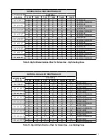

29
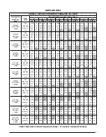
GDD80A - DOWNFLOW FURNACES - 80+ AFUE
Model Number
&
Heating Input
(Btuh)
Motor
Speed
External Static Pressure (Inches Water Column)
0.1
0.2
0.3
0.4
0.5
0.6
0.7
0.8
CFM
Rise
CFM
Rise
CFM
Rise
CFM
Rise
CFM
Rise
CFM
Rise
CFM
Rise
CFM
Rise
054A3XE
(54,000)
High*
1,375
29
1,340
30
1,300
31
1,270
31
1,225
33
1,175
34
1,115
36
1,035
39
Med-High
1,155
35
1,130
35
1,110
36
1,085
37
1,055
38
1,015
39
975
41
910
44
Med-Low**
790
51
775
52
765
52
750
53
730
55
700
57
665
60
610
66
Low
650
62
640
63
630
63
610
66
590
68
565
71
530
75
480
83
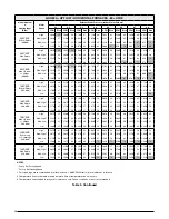
072B4XE
(72,000)
High*
1,675
32
1655
32
1640
33
1620
33
1590
34
1560
35
1520
35
1475
36
Med-High
1,330
40
1315
41
1300
41
1280
42
1255
42
1230
44
1200
44
1150
46
Med-Low**
1,180
45
1165
46
1150
46
1135
47
1115
48
1090
50
1060
50
1010
53
Low
940
57
925
58
900
59
880
61
850
63
825
65
795
67
760
70
090B4XE
(90,000)
High*
1,610
41
1590
42
1575
42
1560
43
1540
43
1495
46
1460
46
1415
47
Med-High
1,295
51
1275
52
1260
53
1250
53
1220
55
1195
57
1170
57
1120
60
Med-Low**
1,155
58
1235
54
1115
60
1095
61
1065
63
1040
66
1015
66
980
68
Low
910
73
885
75
860
78
835
80
810
82
785
85
765
87
735
91
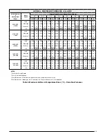
108C5XE
(108,000)
High*
2,395
33
2,335
34
2,285
35
2,230
36
2,200
36
2,140
37
2,080
38
2,000
40
Med-High
2,190
37
2,135
37
2,115
38
2,080
38
2,030
39
1,975
41
1,915
42
1,810
44
Med-Low**
1,785
45
1,770
45
1,740
46
1,725
46
1,685
47
1,645
49
1,615
50
1,565
51
Low
1,145
70
1,110
72
1,070
75
1,035
77
1,000
80
950
84
905
88
835
96
126D5XE
(126,000)
High*
2,445
38
2,395
39
2,385
39
2,330
40
2,275
41
2,225
42
2,130
44
2,015
46
Med-High
2,195
43
2,170
43
2,140
44
2,120
44
2,090
45
2,030
46
1,975
47
1,855
50
Med-Low**
1,795
52
1,780
52
1,770
53
1,760
53
1,725
54
1,690
55
1,655
56
1,610
58
Low
1,480
63
1,475
63
1,450
64
1,440
65
1,440
65
1,415
66
1,405
66
1,375
68
NOTES:
* Factory Set Cooling Speed
** Factory Set Heating Speed
1. Temperature rises in the table are approximate. Actual temperature rises may vary.
2. Temperature rises shaded gray are for reference only. These conditions are not recommended.
Table 4. Maximum Airflow & Temperature Rises (° F) - Downflow Furnaces


