


T12
20
A1979
−
10.0 en
HBM
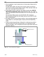
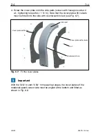
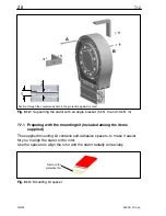
1. Prior to installation, clean the plane faces of the transducer flange and the
counter flange.
For safe torque transfer, the faces must be clean and free from grease.
Use a piece of cloth or paper soaked in solvent. When cleaning, make sure
that you do not damage the transmitter coils.
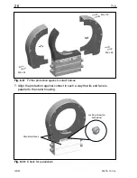
2. For the flange B screw connection, use hexagon socket screws
DIN EN
ISO 4762 of property class 10.9
(measuring ranges 3 kN
@
m to 10 kN
@
m:
12.9) of the appropriate length (depending on the connection geometry, see
Table 6.1).
We recommend fillister-head screws DIN EN ISO 4762, blackened,
smooth-headed, permitted size and shape variance as per DIN ISO 4759,
Part 1, product class A.
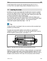
3. First tighten all the screws crosswise with 80% of the prescribed tightening
torque (Table 6.1), then tighten again crosswise, with the full tightening
torque.
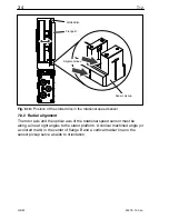
4. There are relevant tapped holes on flange A for continuing the shaft train
mounting. Again use screws of property class 10.9 (measuring ranges
3 kN
m to 10 kNVm: 12.9), and tighten them with the prescribed moment as
specified in Table 6.1.
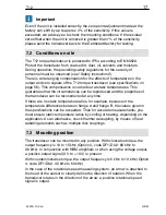
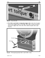
Fastening screw Z
Flange A
Fastening screw Z
Fig. 6.3:
Screw connections, flange A
Содержание T12
Страница 1: ...A1979 10 0 en Digital Torque Transducer T12 Mounting Instructions ...
Страница 2: ......
Страница 89: ...89 T12 A1979 10 0 en HBM ...
Страница 90: ...T12 90 A1979 10 0 en HBM ...
Страница 91: ......


