background image

Hottinger Baldwin Messtechnik GmbH
Im Tiefen See 45
D-64293 Darmstadt
Tel. +49 6151 803-0
Fax +49 6151 803-9100
[email protected]
www.hbm.com

Mat.: 7-0111.0009
DVS: A03729_03_YI0_01 HBM: public
07.2020

E

 Hottinger Baldwin Messtechnik GmbH.

Subject to modifications.
All product descriptions are for general information only.
They are not to be understood as a guarantee of quality or
durability.

Änderungen vorbehalten.
Alle Angaben beschreiben unsere Produkte in allgemeiner
Form. Sie stellen keine Beschaffenheits- oder Haltbarkeits­
garantie dar.

Sous réserve de modifications.
Les caractéristiques indiquées ne décrivent nos produits
que sous une forme générale. Elles n'impliquent aucune
garantie de qualité ou de durablilité.

Con riserva di modifica.
Tutti i dati descrivono i nostri prodotti in forma generica e non
implicano alcuna garanzia di qualità o di durata dei prodotti
stessi.

Содержание C9C

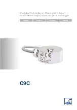
Страница 1: ...Mounting Instructions Montageanleitung Notice de montage Istruzioni per il montaggio English Deutsch Fran ais Italiano C9C...

Страница 2: ...derstood as a guarantee of quality or durability nderungen vorbehalten Alle Angaben beschreiben unsere Produkte in allgemeiner Form Sie stellen keine Beschaffenheits oder Haltbarkeits garantie dar Sou...

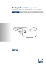
Страница 3: ...Mounting Instructions Montageanleitung Notice de montage Istruzioni per il montaggio English Deutsch Fran ais Italiano C9C...

Страница 4: ...hanical installation 16 6 1 Important precautions during installation 16 6 2 General installation guidelines 16 7 Electrical connection 20 7 1 Connection to measuring amplifier without permanently con...

Страница 5: ...C9C A03729_03_YI0_01 HBM public 3 8 Dimensions 26 9 Specifications 29 9 1 Versions and ordering numbers 33...

Страница 6: ...fety components Please also refer to the Additional safety precautions section Proper and safe operation of force transducers requires proper transportation correct storage setup and mounting and care...

Страница 7: ...e to equipment the user must take appropriate additional safety precautions that meet at least the applicable safety and accident prevention regulations e g automatic emergency shutdown overload prote...

Страница 8: ...gage sensors require electronic amplification and measurement chains require further signal processing Equipment planners installers and operators should always plan implement and respond to the safe...

Страница 9: ...tal protection and material recovery and recycling regulations old transducers that can no longer be used must be disposed of separately and not with normal household garbage If you require more infor...

Страница 10: ...t up ground and label circuits and equipment in accordance with safety engineering standards During use compliance with the legal and safety requirements for the relevant application is also essential...

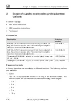
Страница 11: ...168 5 KAB168 20 PUR connection cable with M12 8 pin socket 20 m long free ends on opposite side For connecting the amplifier module to the downstream electronics 1 KAB168 20 Thrust piece EDO9 20kN sui...

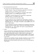
Страница 12: ...signal This option is only available with 1 5 m and 3 m cable lengths The force transducer can also be ordered with a permanently connected amplifier electronics module which converts the output sign...

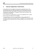
Страница 13: ...ular care must be taken during transportation and installation Dropping and knocking the transducer may cause permanent damage C9C series force transducers have a convex force application part to whic...

Страница 14: ...ible for parasitic forces and moments e g lateral forces and eccentricity influences as well as the effects of temperature 4 2 Strain gage covering agent To protect the SG the force transducers have t...

Страница 15: ...ublic 13 Fig 4 1 The underside of the transducer is fitted with a thin metal plate to protect the strain gages In versions with nominal rated forces up to 200 N there is also a metal plate on the top...

Страница 16: ...t not be allowed to set up a force shunt i e slight movement of the force transducer must not be prevented 5 2 Moisture and corrosion protection The force transducers are hermetically encapsulated and...

Страница 17: ...t not be allowed to accumulate sufficiently to divert some of the measuring force around the force transducer thus invalidating the measured value Force shunt The relevant areas are marked in Fig 5 1...

Страница 18: ...d below the transducer S Make sure that the transducer is not overloaded WARNING There is a danger of the transducer breaking if it is overloaded This can cause danger for the operating personnel of t...

Страница 19: ...n bending moments due to eccentric force application and torques see the Specifications section 9 on page 29 and the maximum permissible loading capacity of the force application parts used possibly p...

Страница 20: ...force application part and the substructure Please also note that the sub structure must ensure that force is always applied to the transducer vertically i e there must be no inclination even under fu...

Страница 21: ...equirements must also be imposed on the structural component that takes the base of the force transducer or on which the C9C is placed S We recommend a flat paint free and grease free surface The clea...

Страница 22: ...signal 3 Blue excitation voltage Cable shield connected to the housing Fig 7 1 Pin assignment and color code The output signal is positive with this pin assignment and load in the pressure direction...

Страница 23: ...with seven wires as in this case a so called one wire TEDS is fitted and this requires two additional wires With extension cables ensure that the connection is perfect with a low contact resistance an...

Страница 24: ...an additional DAkkS national accreditation body for the Federal Republic of Germany calibration is ordered the calibration results are also stored in the TEDS chip The TEDS chip is executed in a zero...

Страница 25: ...ive to interference Note that the thread of the M12 device plug by which you make the connection to the next link in the measurement chain is also electrically connected to the amplifier housing and s...

Страница 26: ...ine amplifier zeroing the measurement chain The measurement starts as soon as the sensor is connected to a supply voltage and the output of the amplifier is connected to the next link in the measureme...

Страница 27: ...rical connection C9C A03729_03_YI0_01 HBM public 25 The zero point is not permanently stored in the device If you have disconnected the measurement chain from the supply voltage we recommend zeroing a...

Страница 28: ...ing radius R10 X G G U R T B 0 3 A 10 5 3 5 18 G SW9 J H 15 3x120 U R B T A 5 18 10 5 J H 3 3x120 4x90 45 Min bending radius R10 Dimensions in mm Fig 8 1 Dimensions of C9C Nominal rated force of C9C A...

Страница 29: ...ns C9C A03729_03_YI0_01 HBM public 27 Cable length to transducer 3 Bending radius min R10mm Plug M12 A coded 8 pins male 50 21 6 26 42 32 40 56 5 Dimensions in mm Fig 8 2 Dimensions of inline amplifie...

Страница 30: ...tering A 0 1 Centering A 0 1 Nominal rated force 0 5 20 kN Nominal rated force 50 kN B 0 1 D 18 F C 11 6 E F B 0 1 D C E 18 Fig 8 3 Dimensions of EDO9 EDO9 Force range A B C D E F mm 1 EDO9 20kN 0 5 2...

Страница 31: ...sensitivity In the nominal rated temperature range TCS 10 K 0 2 In the operating temperature range 0 50 Temperature coefficient of zero signal In the nominal rated temperature range TC0 10 K 0 2 In th...

Страница 32: ...50 Breaking force FB of Fnom 400 Permissible eccentricity when loaded with nominal rated force eg mm 2 6 2 5 2 5 3 5 2 6 3 2 1 8 2 0 0 8 2 5 Nominal rated displacement 15 Snom mm 0 009 0 015 0 019 0 0...

Страница 33: ...e linearity error 0 01 Effect of temperature on zero point 0 15 Rated electrical output Output signal 0 10 V 4 20 mA Nominal rated output 10 V 16 mA Rated output tolerance 0 1 V 0 16 mA Zero signal 0...

Страница 34: ...Vibrational stress to IEC 60068 2 27 Frequency range Hz 5 65 Duration min 30 Acceleration m s2 150 General information Housing material Aluminum Weight without cable g 125 Maximum cable length for sup...

Страница 35: ...t TEDS chip S 5m 05m0 Male connector MS3106PEMV N 6m 06m0 15 pin Sub HD connector Q 7m 07m0 With inline amplifier 0 10 V VA1 12m 12m0 With inline amplifier 4 20 mA VA2 K C9C 05k0 12m0 F T All cable le...

Страница 36: ...Specifications 34 A03729_03_YI0_01 HBM public C9C...

Страница 37: ...Mounting Instructions Montageanleitung Notice de montage Istruzioni per il montaggio English Deutsch Fran ais Italiano C9C...

Страница 38: ...rungen 15 6 Mechanischer Einbau 16 6 1 Wichtige Vorkehrungen beim Einbau 16 6 2 Allgemeine Einbaurichtlinien 16 7 Elektrischer Anschluss 20 7 1 Anschluss an Messverst rker ohne fest angeschlossenes Ve...

Страница 39: ...C9C A03729_03_YI0_01 HBM public 3 8 Abmessungen 26 9 Technische Daten 29 9 1 Ausf hrungen und Bestellnummern 33...

Страница 40: ...ls Sicherheitsbauteile bestimmt Bitte beachten Sie hierzu den Abschnitt Zus tzliche Sicherheitsvorkehrungen Der einwandfreie und sichere Betrieb der Kraftaufnehmer setzt sachgem en Transport fachgerec...

Страница 41: ...e zu tragen hat Wo bei Bruch oder Fehlfunktion der Kraftaufnehmer Menschen oder Sachen zu Schaden kommen k nnen m ssen vom Anwender geeignete zus tzliche Sicherheitsvorkehrungen getroffen werden die z...

Страница 42: ...rs deckt nur einen Teilbereich der Kraftmesstechnik ab da Messungen mit resistiven DMS Sensoren eine elektronische Verst rkung voraussetzen und Messketten eine weitere Signal verarbeitung ben tigen Si...

Страница 43: ...esultierende Sch den aus Wartung Kraftaufnehmer der Serie C9C sind wartungsfrei Entsorgung Nicht mehr gebrauchsf hige Aufnehmer sind gem den nationalen und rtli chen Vorschriften f r Umweltschutz und...

Страница 44: ...ratur der Automatisierungsanlagen bef higt Au erdem haben Sie die Berechtigung Stromkreise und Ger te gem den Normen der Sicherheitstechnik in Betrieb zu nehmen zu erden und zu kennzeichnen Bei der Ve...

Страница 45: ...8 5 KAB168 20 PUR Anschlusskabel mit M12 Buchse 8 polig 20 m lang Gegenseite mit freien Enden Zur Verbindung des Verst r kermoduls mit nachfolgender Elektronik 1 KAB168 20 Druckst ck EDO9 20kN passend...

Страница 46: ...ion ist nur mit den Kabell ngen 1 5 m und 3 m verf gbar Der Kraftaufnehmer kann ebenfalls mit einer fest angeschlossenen Verst rkerelektronik bestellt werden die das Ausgangssignal des Kraft aufnehmer...

Страница 47: ...keit erfordert Transport und Einbau St e und St rze k nnen zu permanenten Sch den am Aufnehmer f hren Die Kraftaufnehmer der Serie C9C weisen eine ballige Krafteinleitung auf in die die zu messenden K...

Страница 48: ...o gew hlt das parasit re Kr fte und Momente z B Querkr fte und Exzentrizit tseinfl sse sowie Tempera tureinfl sse weitestgehend kompensiert werden 4 2 DMS Abdeckung Zum Schutz der DMS verf gen die Kra...

Страница 49: ...Abb 4 1 Die Unterseite des Aufnehmers ist mit einem d nnen Blech zum Schutz der Dehnungsmessstreifen ausgestattet Bei den Versionen mit Nennkr ften bis 200 N befindet sich auch ein Blech an der Obers...

Страница 50: ...keinen Kraftnebenschluss bilden d h die geringf gige Bewegung des Kraftauf nehmers darf nicht behindert werden 5 2 Feuchtigkeits und Korrosionsschutz Die Kraftaufnehmer sind hermetisch gekapselt und...

Страница 51: ...nicht so ansammeln dass sie einen Teil der Messkraft um den Kraftaufnehmer herumleiten und da durch den Messwert verf lschen Kraftnebenschluss Die betreffenden Stellen sind in der Abb 5 1 markiert Ab...

Страница 52: ...r dass der Aufnehmer nicht berlastet wird WARNUNG Bei einer berlastung des Aufnehmers besteht die Gefahr dass der Auf nehmer bricht Dadurch k nnen Gefahren f r das Bedienpersonal der Anlage auftreten...

Страница 53: ...e Krafteinleitung und Drehmomente siehe Technische Daten Kapitel 9 Seite 29 und die maximale zul ssige Belastbarkeit der verwendeten eventuell kundenseitigen Krafteinleitungsteilen Die Krafteinleitung...

Страница 54: ...er Unterkonstruktion abh ngt Beachten Sie bitte auch dass die Unterkonstruktion garantieren muss dass die Kraft stets senkrecht in den Aufnehmer geleitet wird d h auch unter voller Belastung darf es n...

Страница 55: ...ellt werden an das der Boden des Kraftaufnehmers wird bzw auf das die C9C gestellt wird S Wir empfehlen eine ebene lackfreie und fettfreie Oberfl che Die Reinigung kann z B mit dem Reinigungsmittel RM...

Страница 56: ...Verschaltung 1 wei Messsignal 2 schwarz Speisespannung 4 rot Messsignal 3 blau Speisespannung Kabelschirm verbunden mit Geh use Abb 7 1 Anschlussbelegung und Farbcode Bei dieser Anschlussbelegung ist...

Страница 57: ...pitel 9 auf Seite 29 dieser Anleitung Bedenken Sie bitte dass ein Verl ngerungskabel ber sechs Adern verf gen muss Eine solche Verl ngerung hat keinen Einfluss auf die Messung Haben Sie als Stecker di...

Страница 58: ...TEDS ausgeliefert werden der dann im Steckergeh use montiert und verschaltet ist und von HBM vor Auslieferung beschrieben wird Wird der Kraftaufnehmer mit Pr fprotokoll bestellt so werden die Kennwer...

Страница 59: ...des M12 Steckers mittels dem Sie die Ver bindung zum n chsten Glied der Messkette herstellen ebenfalls galvanisch mit dem Verst rkergeh use und somit letztlich mit dem Sensorgeh use verbunden ist Soll...

Страница 60: ...chfolgenden Glied der Messkette verbindet darf 30 m nicht berschreiten 7 2 3 Betrieb des Inline Verst rkers Nullsetzen der Messkette Die Messung startet sobald der Sensor mit einer Versorgungsspannung...

Страница 61: ...ette Nullsetzen k nnen Sollte bereits eine Vorlast auf den Kraftaufnehmer wirken ist dies unbedingt zu beachten da sonst der Kraftaufnehmer berlastet werden kann Der Nullpunkt wird nicht dauerhaft im...

Страница 62: ...s R10 X G G U R T B 0 3 A 10 5 3 5 18 G SW9 J H 15 3x120 U R B T A 5 18 10 5 J H 3 3x120 4x90 45 Min Biege radius R10 Abmessungen in mm Abb 8 1 Abmessungen C9C Nennkraft der C9C A 0 1 B G 0 1 H J R T...

Страница 63: ...ungen C9C A03729_03_YI0_01 HBM public 27 Kabel zum Auf nehmer 3 Biegeradius min R10mm Stecker M12 A kodiert 8 Pins male 50 21 6 26 42 32 40 56 5 Abmessungen in mm Abb 8 2 Abmessungen Inline Verst rker...

Страница 64: ...ngen in mm Zentrier A 0 1 Zentrier A 0 1 Nennkraft 0 5 20 kN Nennkraft 50 kN B 0 1 D 18 F C 11 6 E F B 0 1 D C E 18 Abb 8 3 Abmessungen EDO9 EDO9 Kraftbereich A B C D E F mm 1 EDO9 20kN 0 5 20 kN 8 1...

Страница 65: ...Nenntemperaturbereich TKC 10 K 0 2 Im Gebrauchstemperatur bereich 0 50 Temperatureinfluss auf das Nullsignal Im Nenntemperaturbereich TK0 10 K 0 2 Im Gebrauchstemperatur bereich 0 50 Elektrische Kennw...

Страница 66: ...2 6 3 2 1 8 2 0 0 8 2 5 Nennmessweg 15 Snom mm 0 009 0 015 0 019 0 020 0 025 0 040 0 055 0 075 Grundresonanzfrequenz fG kHz 7 3 10 15 7 3 5 5 7 13 15 1 20 12 Relative zul ssige Schwingbeanspruchung F...

Страница 67: ...4 mA Bereich des Ausgangssignals 0 3 11 V 3 21 mA Grenzfrequenz 3 dB kHz 2 Versorgungsspannung V 19 30 Nennversorgungsspannung V 24 Maximal Stromaufnahme mA 15 30 Temperatur Nenntemperaturbereich C 1...

Страница 68: ...Technische Daten 32 A03729_03_YI0_01 HBM public C9C Modultyp VA2 VA1 Maximale Kabell nge f r Versorgungs spannung Ausgangssignal m 30 Schutzart nach EN 60529 IP67...

Страница 69: ...Stecker MS3106PEMV N 6m 06m0 15 poliger Sub HD Stecker Q 7m 07m0 Mit Inline Verst rker 0 10 V VA1 12m 12m0 Mit Inline Verst rker 4 20 mA VA2 K C9C 05k0 12m0 F T Alle Kabell ngen sind mit allen Stecker...

Страница 70: ...Technische Daten 34 A03729_03_YI0_01 HBM public C9C...

Страница 71: ...Mounting Instructions Montageanleitung Notice de montage Istruzioni per il montaggio English Deutsch Fran ais Italiano C9C...

Страница 72: ...s 15 6 Montage m canique 16 6 1 Pr cautions importantes lors du montage 16 6 2 Directives de montage g n rales 16 7 Raccordement lectrique 20 7 1 Raccordement un amplificateur de mesure sans module am...

Страница 73: ...C9C A03729_03_YI0_01 HBM public 3 8 Dimensions 26 9 Caract ristiques techniques 29 9 1 Versions et num ros de commande 33...

Страница 74: ...as destin s tre mis en uvre comme l ments de s curit Reportez vous ce sujet au paragraphe Mesures de s curit suppl mentaires Afin de garantir un fonctionnement parfait et en toute s curit des capteurs...

Страница 75: ...ectives pour la pr vention des accidents du travail dit es par les caisses professionnelles d assurance accident Mesures de s curit suppl mentaires Les capteurs de force ne peuvent d clencher en tant...

Страница 76: ...ndommag s ou d truits En cas de surcharges notamment un capteur de force peut se briser La rupture d un capteur de force peut endommager des biens ou blesser des personnes se trouvant proximit de ce d...

Страница 77: ...e des informations importantes concernant le produit ou sa manipulation sont fournies Conseil Ce marquage est associ des conseils d utilisation ou autres informations utiles Mise en valeur Voir Les ca...

Страница 78: ...eurs des installations d automatisation et ont t form es pour pouvoir utiliser les installations Elles savent comment utiliser les appareils et technologies d crits dans le pr sent document S En tant...

Страница 79: ...68 5 KAB168 20 c ble de liaison PUR avec embase femelle M12 8 p les 20 m de long c t oppos avec extr mit s libres Pour relier le module amplificateur l lectronique qui suit 1 KAB168 20 Pi ce d appui E...

Страница 80: ...Cette option est uniquement disponible avec les longueurs de c ble 1 5 m et 3 m Le capteur de force peut galement tre achet avec une lectronique d amplification fixe qui transforme le signal de sorti...

Страница 81: ...e r alis s avec un soin particulier Les chocs et les chutes risquent de provoquer un endommagement irr versible du capteur Les capteurs de force de la s rie C9C pr sentent une surface convexe d introd...

Страница 82: ...rces et moments parasites par ex les forces transverses et les influences de l excentricit ainsi que les influences de temp rature 4 2 Recouvrement des jauges Pour prot ger les jauges les capteurs de...

Страница 83: ...M public 13 Fig 4 1 Le fond du capteur est dot d une fine plaque pour prot ger les jauges d extensom trie Pour les versions d une force nominale jusqu 200 N une plaque est galement install e sur le de...

Страница 84: ...ils ne doivent pas provoquer de shunt c est dire emp cher le moindre mouvement du capteur de force 5 2 Protection contre l humidit et la corrosion Les capteurs de force sont ferm s herm tiquement et...

Страница 85: ...e doivent pas s accumuler de mani re d vier une partie de la force de mesure autour du capteur de force et ainsi fausser la valeur de mesure shunt Les zones concern es sont rep r es sur la Fig 5 1 Fig...

Страница 86: ...pas surcharg AVERTISSEMENT En cas de surcharge du capteur ce dernier risque de se briser Ceci risque de mettre en danger les op rateurs de l installation contenant le capteur ainsi que les personnes s...

Страница 87: ...ion excentr e de la force et couples voir Caract ristiques techniques chapitre 9 page 29 ainsi que de la capacit de charge maximale des pi ces d introduction de la force utilis es le cas ch ant fourni...

Страница 88: ...force et de la structure porteuse Notez galement que la structure porteuse doit garantir que la force sera toujours introduite verticalement dans le capteur Ainsi m me pleine charge la position ne do...

Страница 89: ...u capteur de force ou sur laquelle le C9C est pos doit remplir les exigences suivantes S Nous recommandons une surface plane exempte de peinture et de graisse Il est possible de la nettoyer avec le pr...

Страница 90: ...noir tension d alimentation 4 rouge signal de mesure 3 bleu tension d alimentation Blindage du c ble reli au bo tier Fig 7 1 Code de raccordement et de couleur Avec ce code de raccordement le signal d...

Страница 91: ...ion Sub HD pour le Quantum X associ e l option TEDS vous devez alors rallonger sept fils car dans ce cas un OneWire TEDS n cessitant deux fils suppl mentaires est mont Pour les rallonges veillez imp r...

Страница 92: ...ivraison Si le capteur de force est command avec protocole d essai les valeurs caract ristiques du protocole d essai sont inscrites sur la puce TEDS Si un talonnage DAkkS a t command en compl ment les...

Страница 93: ...tage du connecteur m le M12 avec lequel vous tablissez la liaison avec l l ment suivant de la cha ne de mesure doit galement tre reli galvaniquement au bo tier de l amplificateur et de ce fait au bo t...

Страница 94: ...en ligne l l ment suivant de la cha ne de mesure ne doit pas d passer 30 m 7 2 3 Fonctionnement de l amplificateur en ligne Mise z ro de la cha ne de mesure La mesure d marre d s que le capteur est re...

Страница 95: ...e Si le capteur de force est d j soumis une pr charge cela doit tre imp rativement effectu afin d viter toute surcharge du capteur de force Le point z ro n est pas enregistr de mani re permanente dan...

Страница 96: ...bure mini R10 X G G U R T B 0 3 A 10 5 3 5 18 G s p 9 J H 15 3x120 U R B T A 5 18 10 5 J H 3 3x120 4x90 45 Rayon de courbure mini R10 Dimensions en mm Fig 8 1 Dimensions C9C Force nominale du C9C A 0...

Страница 97: ...9C A03729_03_YI0_01 HBM public 27 C ble vers capteur 3 Rayon de courbure min R10mm Connecteur M12 codage A m le 8 broches 50 21 6 26 42 32 40 56 5 Dimensions en mm Fig 8 2 Dimensions module amplificat...

Страница 98: ...centrage A 0 1 centrage A 0 1 Force nominale 0 5 20 kN Force nominale 50 kN B 0 1 D 18 F C 11 6 E F B 0 1 D C E 18 Fig 8 3 Dimensions EDO9 EDO9 Plage de force A B C D E F mm 1 EDO9 20kN 0 5 20 kN 8 1...

Страница 99: ...nominale de temp rature TCS 10K 0 2 Dans la plage d utilisation en temp rature 0 50 Influence de la temp rature sur le z ro Dans la plage nominale de temp rature TC0 10K 0 2 Dans la plage d utilisatio...

Страница 100: ...400 Excentricit admissible en cas de charge la force nominale eg mm 2 6 2 5 2 5 3 5 2 6 3 2 1 8 2 0 0 8 2 5 D placement nominal 15 Snom mm 0 009 0 015 0 019 0 020 0 025 0 040 0 055 0 075 Fr quence fo...

Страница 101: ...de la temp rature sur le z ro 0 15 Caract ristiques lectriques Signal de sortie 0 10 V 4 20 mA Sensibilit nominale 10 V 16 mA Tol rance de sensibilit 0 1 V 0 16 mA Signal z ro 0 V 4 mA Plage du signal...

Страница 102: ...trainte ondul e selon EN 60068 2 27 Plage de fr quence Hz 5 65 Dur e min 30 Acc l ration m s2 150 Indications g n rales Mat riau du bo tier Aluminium Poids sans c ble g 125 Longueur de c ble maximale...

Страница 103: ...Raccordement lectrique Identification du capteur 1 5 m 01m5 Extr mit s libres Y Avec TEDS T 3 m 03m0 Connecteur Sub D 15 p les F Sans TEDS S 5 m 05m0 Connecteur MS3106PEMV N 6 m 06m0 Connecteur Sub H...

Страница 104: ...avec une option comprenant un connecteur m le La combinaison TEDS c ble extr mit s libres n est pas possible Les versions avec amplificateurs de mesure en ligne VA1 et VA2 ne peuvent tre combin es qu...

Страница 105: ...Mounting Instructions Montageanleitung Notice de montage Istruzioni per il montaggio English Deutsch Fran ais Italiano C9C...

Страница 106: ...Montaggio meccanico 16 6 1 Misure importanti per il montaggio 16 6 2 Direttive generali per il montaggio 16 7 Collegamento elettrico 20 7 1 Collegamento all amplificatore di misura senza modulo ampli...

Страница 107: ...C9C A03729_03_YI0_01 HBM public 3 8 Dimensioni 26 9 Dati tecnici 29 9 1 Versioni e No Ordine 33...

Страница 108: ...ito consultare anche il paragrafo Misure di sicurezza supplementari Il funzionamento corretto e sicuro dei trasduttori di forza presuppone che il trasporto il magazzinaggio l installazione ed il monta...

Страница 109: ...mpianto Nei casi in cui la rottura o il malfunzionamento dei trasduttori di forza possa provocare danni alle persone o alle cose l utente deve prendere opportune misure di sicurezza addizionali che so...

Страница 110: ...n trasduttori ad ER resistivi presuppongono un amplificazione elettronica e le catene di misura necessitano di un ulteriore gestione del segnale I progettisti gli allestitori e i gestori dell impianto...

Страница 111: ...duttore modifiche dal punto di vista strutturale e della sicurezza Qualsiasi modifica annulla la nostra eventuale responsabilit per i danni che ne potrebbero derivare Manutenzione I trasduttori di for...

Страница 112: ...iliarit con l uso della strumentazione e delle tecnologie descritte in questa documentazione S incaricato della messa in funzione o degli interventi di assistenza e ha conseguito una formazione profes...

Страница 113: ...folgender Elektronik 1 KAB168 5 KAB168 20 PUR Anschlusskabel mit M12 Buchse 8 polig 20 m lang Gegenseite mit freien Enden Zur Verbindung des Verst r kermoduls mit nachfolgender Elektronik 1 KAB168 20...

Страница 114: ...V Questa opzione disponibile solo con le lunghezze cavo di 1 5 m e 3 m Il trasduttore di forza pu essere ordinato anche con elettronica amplificatore collegata in modo fisso che trasforma il segnale...

Страница 115: ...d il montaggio richiedono particolare attenzione Urti o cadute possono danneggiare permanentemente il trasduttore I trasduttori di forza della serie C9C dispongono di un elemento d introduzione della...

Страница 116: ...le forze laterali e l influenza dell eccentricit oltre che l effetto della temperatura 4 2 Materiale di rivestimento degli ER Per proteggere gli ER i trasduttori di forza dispongono di una sottile lam...

Страница 117: ...Il lato inferiore del trasduttore munito di una sottile lamina metallica per proteggere gli estensimetri Nelle versioni con forze nominali fino a 200 N anche il lato superiore del trasduttore munito d...

Страница 118: ...e derivazioni della forza poich non deve essere impedita la pur minima deflessione di misura del trasduttore di forza 5 2 Protezione da umidit e corrosione I trasduttori di forza sono ad incapsulatura...

Страница 119: ...no accumulare sul trasduttore in quanto deviano la forza di misura attorno al trasduttore di forza falsando il valore di misura derivazione della forza Le zone interessate sono contrassegnate in Fig 5...

Страница 120: ...on venga sovraccaricato AVVERTIMENTO Nel caso di sovraccarico esiste il rischio di rottura del trasduttore Possono conseguirne pericoli per gli operatori addetti all impianto in cui montato il trasdut...

Страница 121: ...ne della forza eccentrica e coppie vedere i Dati tecnici nel capitolo 9 a pagina 29 e la portata massima ammissibile degli elementi d introduzione della forza usati eventualmente lato cliente L introd...

Страница 122: ...a e da quella della struttura sottostante Considerare inoltre che la struttura inferiore deve garantire che la forza venga sempre introdotta in verticale nel trasduttore cio che la struttura non si fl...

Страница 123: ...i requisiti dell elemento della struttura che diventa la base del trasduttore di forza o su cui viene poggiato il C9C S Si consiglia un superficie piana non verniciata e senza grassi La pulizia pu ess...

Страница 124: ...u tensione di alimentazione Schermo del cavo collegato alla custodia Fig 7 1 Assegnazione dei collegamenti e codice colori Con questa assegnazione dei collegamenti il segnale di uscita positivo con ca...

Страница 125: ...ione SubHD per il QuantumX combinata con l opzione TEDS necessario prolungare sette fili poich in tal caso viene montato il cosiddetto OneWire Teds che necessita di due fili addizionali Se vengono usa...

Страница 126: ...a spedizione Se il trasduttore di forza viene ordinato con la relazione di prova le sensibilit qui riportate vengono salvate nei TEDS Se viene ordinata anche una taratura DAkkS anche i risultati della...

Страница 127: ...a spina M12 con cui viene stabilito il collegamento alla maglia successiva della catena di misura collegato galvanicamente alla custodia dell amplificatore e quindi in fin dei conti alla custodia del...

Страница 128: ...lega l amplificatore Inline alla maglia successiva della catena di misura non deve superare i 30 m 7 2 3 Uso dell amplificatore Inline reset della catena di misura La misurazione inizia non appena il...

Страница 129: ...isca Se sul trasduttore di forza agisce gi un precarico estremamente importante che venga gi considerato poich altrimenti il trasduttore di forza pu essere sovraccaricato Il punto di zero non viene sa...

Страница 130: ...ra min R10 X G G U R T B 0 3 A 10 5 3 5 18 G SW9 J H 15 3x120 U R B T A 5 18 10 5 J H 3 3x120 4x90 45 con raggio di curvatura min R10 Dimensioni in mm Fig 8 1 Dimensioni C9C Forza nominale del C9C A 0...

Страница 131: ...A03729_03_YI0_01 HBM public 27 Cavo del trasduttore 3 Raggio di curvatura min R10 mm Spina M12 codificazione A 8 pin maschio 50 21 6 26 42 32 40 56 5 Dimensioni in mm Fig 8 2 Dimensioni modulo amplif...

Страница 132: ...o A 0 1 centraggio A 0 1 Forza nominale 0 5 20 kN Forza nominale 50 kN B 0 1 D 18 F C 11 6 E F B 0 1 D C E 18 Fig 8 3 Dimensioni EDO9 EDO9 Campo di misura della forza A B C D E F mm 1 EDO9 20kN 0 5 20...

Страница 133: ...tura CTS 10 K 0 2 Nel campo della temperatura di esercizio 0 50 Coefficiente termico dello zero Nel campo nominale di temperatura CT0 10 K 0 2 Nel campo della temperatura di esercizio 0 50 Sensibilit...

Страница 134: ...di rottura FB di Fnom 400 Eccentricit ammissibile con carico con forza nominale eg mm 2 6 2 5 2 5 3 5 2 6 3 2 1 8 2 0 0 8 2 5 Deflessione nominale 15 Snom mm 0 009 0 015 0 019 0 020 0 025 0 040 0 055...

Страница 135: ...linearit 0 01 Coefficiente termico dello zero 0 15 Sensibilit elettriche Segnale di uscita 0 10 V 4 20 mA Sensibilit nominale 10 V 16 mA Tolleranza della sensibilit 0 1 V 0 16 mA Segnale di zero 0 V 4...

Страница 136: ...citazione vibrazionale secondo IEC 60068 2 27 Campo di frequenze Hz 5 65 Durata min 30 Accelerazione m s2 150 Dati generali Materiale della custodia Alluminio Peso senza cavo g 125 Lunghezza cavo mass...

Страница 137: ...6PEMV N 6m 06m0 Spina Sub HD a 15 poli Q 7 m 07m0 Con amplificatore di misura Inline 0 10 V VA1 12 m 12m0 Con amplificatore di misura Inline 4 20 mA VA2 K C9C 05k0 12m0 F T Tutte le spine si possono m...

Страница 138: ...Dati tecnici 34 A03729_03_YI0_01 HBM public C9C...

Страница 139: ...Dati tecnici C9C A03729_03_YI0_01 HBM public 35...

Страница 140: ...www hbm com HBM Test and Measurement Tel 49 6151 803 0 Fax 49 6151 803 9100 info hbm com measure and predict with confidence A03729_03_YI0_01 7 0111 0009 HBM public...

Отзывы: