


10
Plumbing
Ensure that the
AquaRite CUL Electrolytic Chlorine Generato
r
installation does not constitute a cross
connection with the local potable water supply. Consult local plumbing codes.
The
AquaRite CUL Electrolytic Chlorine Generato
r
flow switch and cell should be plumbed in the return
line to the pool/spa. The preferred installation is after (downstream) all the pool equipment (filter, heater,
solar, etc.). The AquaRite Electrolytic Chlorine Generator cell and flow switch tee fitting are designed to be
plumbed into 51mm (2”) PVC pipe. Adapters (not included) can be used for systems with 38mm (1 ½”)
plumbing.
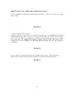
For proper plumbing, refer to the overview diagram on page 9. Alternate configurations #1 shows the flow
switch can also be in front of the
AquaRite CUL Electrolytic Chlorine Generato
r
cell. Configurations #2
and#3 allow for chlorination of both the pool and spa during spa spillover operation, but prevent over
chlorination of the spa during "spa only" operation. Never use configuration #4.
{Diagram}
Flow Switch:
IMPORTANT: There must be at least a 25cm (12”) straight pipe run before (upstream)
the flow switch. If the switch is plumbed after the
AquaRite CUL Electrolytic Chlorine
Generato
r
cell, the
AquaRite CUL Electrolytic Chlorine Generato
r
cell can be counted as
the 25cm (12”) of straight pipe. To ensure proper operation, verify that the arrow on the
flow switch (located on top of gray hex) points in the direction of water flow.
AquaRite CUL
Install using the unions provided. Tighten unions BY HAND for a watertight seal. For
Electrolytic
pool/spa combination systems with spillover, use configurations #2 or #3 above to allow
Chlorine
chlorination of both the pool and spa during spillover but preventing over-chlorination
Generator
when operating the spa only.
Cell


