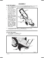
Hayter Powertrim 407F Скачать руководство пользователя страница 9

ASSEMBLY

9

1739579 

RAISE THE HANDLE

1. Hold the

 handle

 with one hand and loosen both 

handle adjustment knobs

 until the ratchet

teeth are disengaged. Do not remove the 

handle adjustment knobs

. See Figure 2.

2. Raise the

 handle

 to the

operating position.

3. Stand  in  the  operator’s

position behind the ma-
chine. Put the

 handle 

in

a  comfortable  position.
Make sure both sides  of
the

 handle

 are level.

NOTE:  Make sure the

cables  are  not  caught

between the upper and

lower handle.

4. Tighten  the 

handle  ad-

justment knobs

.  Make

sure the 

handle pivots

are locked in place.

NOTE:  The handlebar

height  is  adjustable.

See  “How  To  Adjust

The Height Of The Han-

dlebar”  in  the  Mainte-

nance section.

5. To attach the 

recoil start handle

 to the 

rope guide,

 twist the rope through

the 

rope guide

 mounted on the right side of the handlebar.
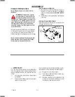
ATTACH THE GUARD

1. Attach the 

guard 

to the 

machine 

with the

four 

fasteners 

as shown. See Figure 3.

Figure 3

Guard

Trimmer

Fastener

Handle

Handle Adjustment

Knob

Handle

Pivot

Recoil Start

Handle

Rope

Guide

Figure 2

Содержание Powertrim 407F

Страница 1: ...POWERTRIM Code 407F OWNER S HANDBOOK P O N L A I R E S E D O C ART NO 111 3445 Rev A 407F 310000001 Issue 10 2009...

Страница 2: ...2 1739579 TABLE OF CONTENTS LIMITED WARRANTY OPERATOR SAFETY ASSEMBLY OPERATION MAINTENANCE TROUBLESHOOTING SPECIFICATIONS REPAIR PARTS 3 4 8 11 14 19 21 23...

Страница 3: ...lade brake units and other such devices are not applicable Only machines fitted with a genuine Hayter friction disc which are used in accordance with the recommended operating and maintenance procedur...

Страница 4: ...t Also wear long trousers Do not wear shorts 8 Do not wear loose clothing or jewelry They can be caught in moving parts 9 Always wear safety goggles or safety glasses with side shields when operating...

Страница 5: ...hanging direction on slopes Do remove objects such as rocks tree limbs etc Do watch for holes ruts or bumps Tall grass can hide obstacles Do not trim near drop offs ditches or em bankments The operato...

Страница 6: ...to do so in this Manual Service and repair proce dures can be done with the machine in an upright position Some procedures will be easier if the machine is lifted on a raised platform or working surf...

Страница 7: ...al Before Operating This Machine 3 WARNING Thrown Objects Keep Bystanders Away Read User Instructions Before Operating This Machine 4 Do Not Trim Up And Down Slopes Trim Across Slopes 5 WARNING Rotati...

Страница 8: ...sembled and positioned in the carton for ship ment References to the right or left hand side of the machine are from the viewpoint of the opera tor s position behind the unit REMOVE THE TRIMMER FROM C...

Страница 9: ...cables are not caught between the upper and lower handle 4 Tighten the handle ad justment knobs Make sure the handle pivots are locked in place NOTE The handlebar height is adjustable See How To Adju...

Страница 10: ...ith Oil 1 Remove the oil fill cap dipstick shown in Figure 4 Fill the crankcase to the FULL line on oil fill cap dipstick DO NOT OVER FILL 2 Install the oil fill cap dipstick and tighten securely Fill...

Страница 11: ...the trimmer head Throttle Control Lever Controls the speed or stops the engine Recoil Starter Handle The engine is equipped with an easy pull recoil starter EYE PROTECTION WARNING Debris thrown from t...

Страница 12: ...n the FAST position to run the engine at full speed 2 Pull the throttle control lever back to de crease engine speed Push the throttle control lever forward to increase engine speed 3 To stop the engi...

Страница 13: ...noxide an odorless and deadly gas Keep hands feet hair and loose clothing away from the machine and any moving parts on the engine Avoid the muffler and surround ing areas Temperatures may ex ceed 150...

Страница 14: ...Lines 1 Check Trimmer Head Engagement Engine Machine Cleaning 2 Check Nuts and Bolts Check Spark Plug Change Engine Oil Service Air Filter 3 Lubricate Jackshaft Assembly Lubricate Wheel Bearings Note...

Страница 15: ...the engine is warm For the proper oil capacity see the en gine manufacturer s instructions 1 Disconnect spark plug wire from the spark plug 2 Remove the oil drain plug as shown in Figure 11 3 Drain a...

Страница 16: ...g 3 Before installing the spark plug coat the threads lightly with oil for easy removal Tighten the spark plug to a torque of 15 foot pounds Figure 12 Spark Plug Feeler Gauge 0 030 ADJUST THE HEIGHT O...

Страница 17: ...im mer line keep the trimmer line moist If not kept moist the nylon trimmer line will be come dry and brittle Keep extra trimmer line in a can of water The line will then stay flexible and easy to cha...

Страница 18: ...immer Completely clean the machine Put the machine in a building that has good ventilation Engine To prevent engine damage when the ma chine is in storage for 30 days or more fol low the steps below L...

Страница 19: ...ne Clean carburetor or fuel line Dirty air filter Replace air filter Carburetor out of adjustment See authorized dealer Engine flooded Wait several minutes before starting Throttle control lever in in...

Страница 20: ...less than 1 2 this length replace the line Engine not set at FAST speed Move engine throttle lever to FAST position Trimmer vibrates Trimmer line lengths are substantially different Adjust trimmer li...

Страница 21: ...rsepower values are derived at 3600 RPM Actual gross engine power will be lower and is affected by among other things ambient operating conditions and engine to engine variability Given both the wide...

Страница 22: ...are available from your local Hayter authorised dealer the store where the mower was purchased or a service shop recommended by the store If you are unable to obtain parts or service in the manner ou...

Страница 23: ...Repair Parts PTS 1...

Страница 24: ...Handle And Wheels NOTE Unless noted otherwise use the standard hardware torque specification chart POWERTRIM Code 407F PTS 2...

Страница 25: ...T Axle 17 MU015X84MA WASHER 18 MU0020X3MA SPACER 19 MU740190MA ASSEMBLY Axle Bracket 20 MU740188MA SCREW 21 MU26X274MA BOLT Carriage 22 MU711935MA DECK 23 MU740150E701MA BOLT 24 MU0025X6MA SHIELD Trai...

Страница 26: ...Cutting Head And Shield NOTE Unless noted otherwise use the standard hardware torque specification chart POWERTRIM Code 407F PTS 4...

Страница 27: ...1 MU740171MA SPACER 12 MU740173MA BELT 13 MU711933MA PULLEY Idler 14 MU740244MA PULLEY Engine 15 MU740179MA PULLEY Idler 16 MU740183MA LOCKWASHER 17 MU018X31MA BOLT 18 MU001X20MA SCREW 19 MU26X235MA G...

Страница 28: ...crews thread forming screws sheet metal screws and socket head setscrews 2 Recommended seating torque values for locknuts a for prevailing torque locknuts use 65 of grade 5 torques b for flange whizlo...

Страница 29: ......

Страница 30: ......

Отзывы: