Assembling and Mounting
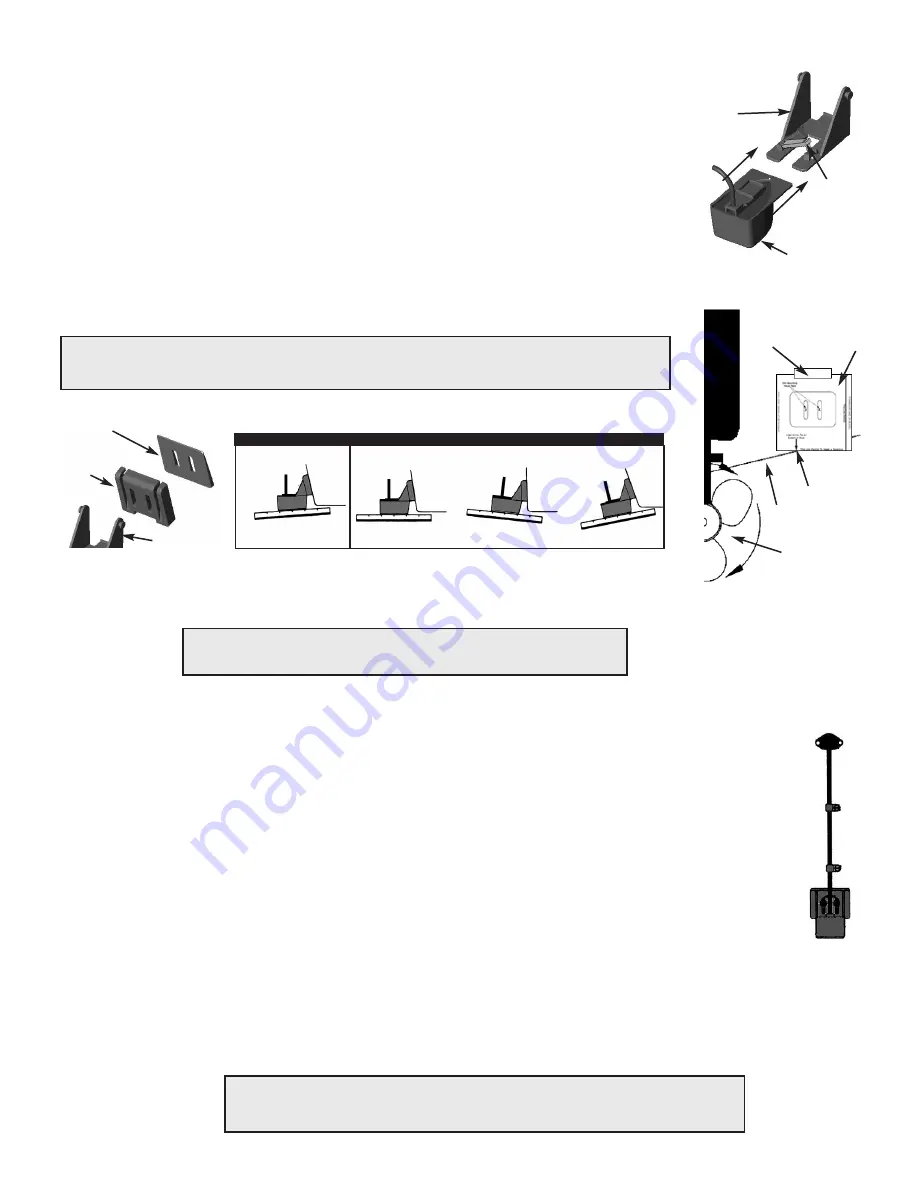
1. With the Locking Tab in the up position, align the transducer and bracket as per Figure 2 and slide the trans-
ducer into the Pivot Bracket until it cannot slide any further. (minimal force is required)
2. Press the Locking Tab down against the Pivot Bracket until it locks firmly into place.
3. Tape the template inserted in this manual against the hull as per Figure 3.
4. At the desired mounting location, position the template so the arrow at the bottom is aligned with the bottom
edge of the vessel making certain that the template is parallel to the waterline of the vessel.
5. Using a 9/64" (4 mm) drill bit, drill two holes 7/8" (22 mm) deep at the locations indicated on the template
marked with an “X”. To prevent drilling too deeply, wrap masking tape around the bit 7/8” (22 mm) from the
point. To minimize surface cracking on fiberglass hulls use a chamfer or countersink bit. If either is not avail-
able, start drilling with a 1/4” (6 mm) bit to a depth of 1/16" (1 mm), then finish the hole with the 9/64” (4mm)
bit.
6. Apply a marine sealant to the threads of the two #10 x 1-1/4" self-tapping screws and screw the bracket to
the hull. DO NOT tighten the screws completely until you position the transducer as per the next section.
Positioning
The bracket is designed for a standard 13
°
transom angle. To determine if the plastic shim is needed, posi-
tion the transducer at the desired location. Using a straight edge, compare the underside of the transducer rela-
tive to the underside of the hull. The stern (trailing edge) of the transducer should be 1/16” – 1/8" (1 – 3 mm)
below the bow (leading edge) of the sensor.
Cable Routing
Route the transducer cable over the transom, through a deck or splash-well drain hole or through a new hole drilled in the transom.
1. If a new hole is required, it MUST be drilled well above the waterline.
2. Mark the desired location with a pencil
3. Check for obstructions behind the desired location inside the hull.
4. Drill a hole through the transom using a 3/4” or 19 mm hole saw or spade bit.
5. Route the cable over or through the transom.
6. On the outside of the hull secure the cable against the transom using the included cable clamps. Evenly distribute the clamps between
the transducer and the location where the cable passes through or over the hull and mark the location with a pencil (Figure 6).
7. At the marked locations, use a 1/8" (3 mm) bit to drill a hole 3/8” (10 mm) deep. To prevent drilling too deeply, wrap masking tape around
the bit 3/8"
8. Apply marine sealant to the threads of the 2 #6 x 1/2" self-tapping screws, position the two cable clamps and fasten them in place. (skip
to #13 if the cable was routed over the transom or a hole that was already in the hull)
9. If a hole has been drilled in the transom position the clam shell cover over the cable where it enters the hull and mark the two screw
holes.
10. Use a 3 mm or 1/8" bit to drill a hole 10 mm (3/8") deep. To prevent drilling too deeply, wrap masking tape around the bit 10 mm (3/8")
from the point of the bit.
11. Fill the remaining space in the hole with marine sealant.
12. Apply marine sealant to the 2 #6 x 1/2" self-tapping screws and fasten the cable clam shell cover into place.
13. Route the cable to the depth sounder to the mounting location of the depth sounder . To reduce electrical interference, separate the transducer cable
from other electrical wiring. Coil any excess cable and secure it in place using tie-wraps.
14. Refer to the depth sounder owner’s manual to connect the transducer to the instrument.
Checking for Leaks
Pivot Bracket
Sensor
Locking
Tab
Figure 2
Figure 3
Tightening
Slide the transducer up or down to provide a projection of 1/8” inches (3 mm) below the hull bottom and then
tighten the screws.
IMPORTANT!!!!
Align the included shims (Figure 4) to achieve a slight angle as per Figure 5 below. To prevent aeration, NEVER
position the transducer is a manner that the Leading Edge (bow) is LOWER than the Trailing Edge (stern).
Figure 5
parallel
Reversed Angle
Too Steep Of An Angle
shim with taper down
C O R R E C T
I N C O R R E C T
slight angle
IMPORTANT!!!!
Do not allow the transducer to extend more than 1/8”(3 mm) of an inch below the
bottom of the boat as this will create increased aeration and turbulence.
Figure 6
WARNING!!!!
When the boat is placed in the water, immediately check for leaks around the screws and any
holes drilled in the hull. Never install a transducer and leave the boat in the water unchecked.
Template
Tape
Hull Bottom
Alignment Arrow
Propeller
Shim
Pivot Bracket
Mounting
Bracket
Figure 4
- 2 -


