


PTO
™
MOD
3
Owner’s Manual
AM-HPTOM3-OM
Rev AB February 2020
7
INSTALLATION
WARNING: THE SHIPPING PALLET MUST BE REMOVED FOR PROPER AND SAFE
OPERATION
Location
For maximum trouble-free service, choose a location which is free of excess moisture, dust and
corrosive fumes. Also, avoid locations where temperatures are high or where liquids will drip on the
charger. Follow charger warning label when mounting on or over a combustible surface. Do not
obstruct the ventilating openings.
Wall/Floor Mount Cabinet Chargers
The charger must be permanently mounted in a vertical position. The lower part of the charger must
be at least 12 inches from the charger below if installed above another charger, and the upper part
12 inches from the ceiling. The distance between two chargers must be no less than 12 inches. Use
the mounting kit supplied with the charger. See the Mounting Dimensions section at the end of this
manual for proper Wall and Floor mounting.
NOTE:
Ambient temperature cannot exceed 113° F (45° C).
Electrical Connections
To prevent failure of the charger, be sure it is connected to the correct line voltage.
WARNING: MAKE SURE THE POWER TO THE CHARGER IS OFF AND THE BATTERY IS
DISCONNECTED BEFORE CONNECTING THE INPUT POWER TO THE TERMINALS OF
THE CHARGER.
Connecting Input Power
Connect the input power to the appropriate terminals,
including ground
. For screw type terminals,
torque to 15 in-lb. Follow your local and National Electric Code in making these connections.
AC Circuit Protection
The user must provide suitable branch circuit protection and a disconnect method from the AC power
supply to the charger to allow for safe servicing.
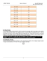
Breaker/Fuse Chart
AC Amps
(A)
Breaker/Fuse size
(A)
1
– 12
15
12.1
– 16
20
16.1
– 20
25
20.1
– 24
30


