English
Form No. GR5ALM-0217
9
INSTALLATION
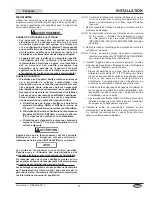
Shelf
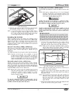
Angle bracket
fastened to
underside of shelf.
1" (25 mm)
Minimum
Gap
Flat Shelf Installation
3. Route the element wire leads and LED wire leads toward
the installation location for the control box/controls.
NOTE: Curved Infrared Strip Heaters with lights (GR5AL Series)
require two separate power supplies from the control
box. A high voltage supply for the heating element and
a low voltage supply for the LED light channels.
Installing the Controls
GR5A and GR5AL Series strip heaters have different control
options. GR5A Series units can be ordered with an RMB Series
Remote Control Box or individual, remote-mounted controls.
GR5AL Series units come standard with a specific remote-
mounted control box. Refer to the appropriate section below for
installation information.
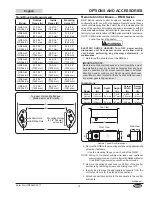
Remote Control Boxes (RMB)—GR5A Series
Hatco Remote Control Boxes (RMB Series) include switches,
wire leads, and/or indicator lights and are shipped ready for
installation.
The RMB Series require one remote control box per strip heater.
NOTE: Remote control boxes are available in several
configurations depending on the model. All boxes are
built in accordance with UL standards to accommodate
switches, indicator lights, and wiring. See the
OPTIONS
AND ACCESSORIES
section for more information.
Remote Mounted Controls—GR5A Series
Optional remote mounted control switches include ON/OFF
(I/O) toggle switches and infinite heat controls. These controls
need to be installed into an approved electrical box/enclosure
(not supplied) by a qualified electrician. See the OPTIONS AND
ACCESSORIES section for more information.
NOTE: When two or more units are mounted where the heat
from one housing tends to raise the temperature of
another, the controls should be installed in a remote
control box. Units in a multiple installation should use
remote mounted controls.
NOTICE
To prevent premature failure of components due to
excessive heat, remote mounted control switches must be
installed outside the strip heater heat zone.
Installing the Control Box—GR5AL Series
Use the following procedure to install the GR5AL Series control
box.
NOTE: Units can be ordered with up to 10ʹ (3 m) of element
wire leads, depending on the installation location of the
control box. The LED wire leads always will be 18" (457
mm) longer than the element wire leads.
WARNING
Control box must be mounted in a vertical surface.
Mounting control box in a horizontal surface may result in
the collection of liquids and lead to electric shock.
NOTICE
Install remote-mounted control box outside of areas
subject to temperatures above 104°F (40°C). Excessive
temperatures will cause controls to overheat, malfunction,
and fail.
IMPORTANT NOTE:
Remote-mounted control boxes and control switches must be
installed in a cool, dry location as far away from any heat zone
as possible. Do not mount control boxes directly on, under, or
above unit. Do not mount control boxes in direct contact with
any heated surface or near any steam generating equipment.
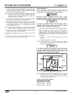
1. Cut and drill the appropriate holes in the vertical surface
where the control box will be installed. Refer to the
illustration below for cutout and screw hole dimensions.
NOTE: Make sure the control box installation location provides
enough space behind the vertical surface for the depth
of the control box and electrical connections.
10-1/8"
(257 mm)
4-3/4"
(121 mm)
10-7/16"
(265 mm)
2-1/2"
(64 mm)
1-1/8″
(29 mm)
7/16″
(11 mm)
3/8″
(9 mm)
Silicone Sealant
Control Box Cutout and Screw Hole Dimensions
NOTE: Make sure the width of the control box cutout does not
exceed the above dimension.
2. Complete the routing of the element wire leads and the
LED wire leads from the unit to meet up with the control box
through the cutout.
NOTE: Curved Infrared Strip Heaters with lights (GR5AL and
GR5AHL models) require two separate power supplies
from the control box. A high voltage supply for the
heating element and a low voltage supply for the LED
light channels.
3. Route the wire leads from the on-site power supply to meet
up with the control box through the cutout.
continued...
Содержание Glo-Ray GR5A
Страница 34: ...English Form No GR5ALM 0217 34 NOTES ...
Страница 35: ...English Form No GR5ALM 0217 35 NOTES ...


