English
Form No. GR5ALM-0217
10
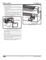
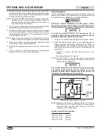
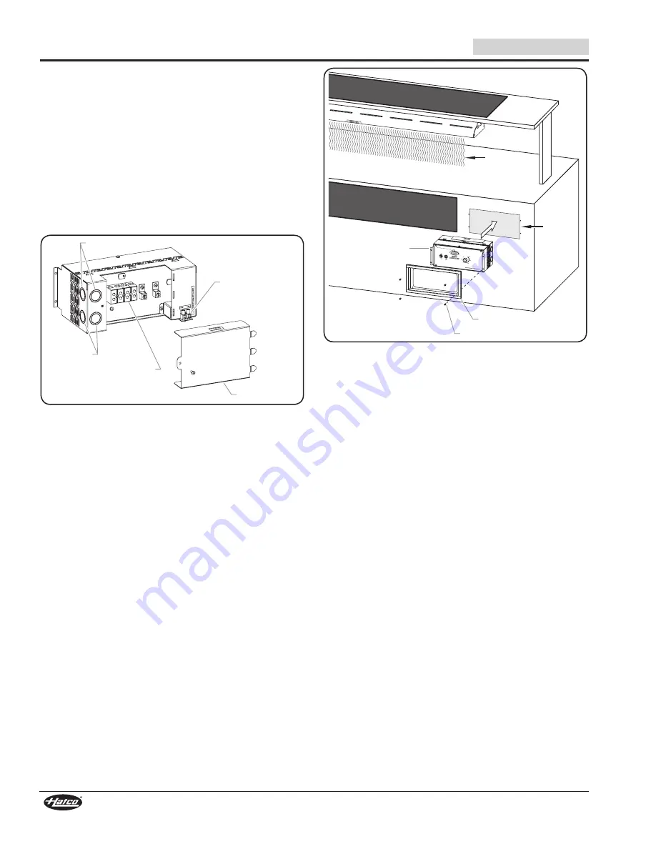
4. Remove the four trim cover screws from the control box,
and remove the trim cover.
5. Have a qualified electrician make the appropriate electrical
connections to the control box. Refer to the wiring diagram
included with the unit.
a. Connect the LED wire leads from the unit to the low
voltage 2-pole terminal block on the outside of the
control box.
b. Connect the element wire leads from the unit, through
a power knockout, to the high voltage 4-pole terminal
block inside the access cover of the control box.
c. Connect the on-site power supply through a power
knockout, to the high voltage 4-pole terminal block inside
the access cover of the control box.
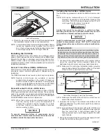
Low Voltage
Terminal Block
Access Cover
Power
Knockouts
Power Knockouts
High Voltage
Terminal Block
(4-Pole)
GR5AL Control Box Electrical Connections
6. Position the control box into the cutout opening through the
front side. Make sure that none of the electrical wires are
pinched or stressed.
7. Fasten the control box to the vertical surface using four
screws (not supplied).
8. Apply a 1/4″ (6 mm) bead of NSF-approved silicone sealant
where the trim cover will contact the cabinet surface. Refer
to the “Control Box Cutout and Screw Hole Dimensions”
illustration for more information.
9. Reinstall the trim cover on the control box and secure in
position using the four trim cover screws. Make sure to
embed the trim cover edge into the silicone.
DO NOT INSTALL BOX
IN THIS AREA
DO NOT INSTALL
BOX IN THIS AREA
Trim Cover
Trim Cover Screw
Control Box
Control
Box
Cutout
Heat
Installing the Control Box
INSTALLATION
Содержание Glo-Ray GR5A
Страница 34: ...English Form No GR5ALM 0217 34 NOTES ...
Страница 35: ...English Form No GR5ALM 0217 35 NOTES ...


