background image

English

Form No. GR5ALM-0217

2

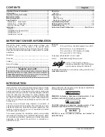
INTRODUCTION

Hatco Glo-Ray

®

 Curved Infrared Strip Heaters keep hot foods 

at optimum serving temperatures longer. The sleek, curved 

design minimizes the strip heaters size while accenting and 

warming the food product below. Specially designed reflectors 

direct the heat from the element to safely maintain peak 

serving temperatures longer without cooking the food beyond 

the point of excellence. Glo-Ray Curved Strip Heaters are 

perfect for front-of-the-house applications such as buffet and 

serving lines.
Glo-Ray Curved Infrared Strip Heaters are products of 

extensive research and field testing. The materials used were 

selected for maximum durability, attractive appearance, and 

optimum performance. Every unit is inspected and tested 

thoroughly prior to shipment.
This manual provides the installation, safety, and operating 

instructions for Glo-Ray Curved Infrared Strip Heaters. Hatco 

recommends all installation, operating, and safety instructions 

appearing in this manual be read prior to installation or 

operation of a unit.

Safety information that appears in this manual is identified by 

the following signal word panels:

WARNING

WARNING indicates a hazardous situation which, if not 

avoided, could result in death or serious injury.

CAUTION

CAUTION indicates a hazardous situation which, if not 

avoided, could result in minor or moderate injury.

NOTICE

NOTICE is used to address practices not related to 

personal injury.

Important Owner Information ..............................................2

Introduction ...........................................................................2

Important Safety Information ..............................................3

Model Description ................................................................4

Model Designation ...............................................................4

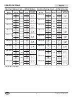
Specifications .......................................................................4

Dimensions 

— 

Strip Heater .................................................4

Dimensions 

— 

Control Box ..................................................5

Electrical Ratings Charts .....................................................5

Installation .............................................................................7

General ................................................................................7

Installation Site Requirements .............................................8

Installing the Unit .................................................................8

Installing the Controls ..........................................................9

Operation ............................................................................. 11

General .............................................................................. 11

Maintenance ........................................................................12

General ..............................................................................12

Daily Cleaning ...................................................................12

Replacing a Display Light ..................................................12

Troubleshooting Guide ......................................................13

Options and Accessories ..................................................14

Limited Warranty ................................................................17

Authorized Parts Distributors ...........................Back Cover

IMPORTANT OWNER INFORMATION

Record the model number, serial number, voltage, and 

purchase date of your strip heater in the spaces below 

(specification label located on the underside of the unit). Please 

have this information available when calling Hatco for service 

assistance.
Model No. ________________________________________
Serial No. _________________________________________
Voltage ___________________________________________
Date of Purchase ___________________________________

Register your unit!

Completing online warranty registration will prevent delay in 

obtaining warranty coverage. Access the Hatco website at 

www.hatcocorp.com

, select the 

Parts & Service

 pull-down 

menu, and click on “Warranty Registration”.

Business

Hours: 7:00 

am

 to 5:00 

pm

 Central Standard Time (CST)


(Summer Hours:  June to September


 7:00 

am

 to 5:00 

pm

 CST Monday

Thursday 

 7:00 

am

 to 4:00 

pm

 CST Friday)

Telephone: 800-558-0607;  414-671-6350
E-mail: [email protected]

24 Hour 7 Day Parts and Service

Assistance available in the United States

and Canada by calling 800-558-0607.

Additional information can be found by visiting our web site at 

www.hatcocorp.com

.

CONTENTS

Содержание Glo-Ray GR5A

Страница 1: ...te manual Cualquier falla en el seguimiento de las instrucciones contenidas en este manual puede resultar en un serio lesión o muerte Este manual contiene importante información sobre seguridad concerniente al mantenimiento uso y operación de este producto Si usted no puede entender el contenido de este manual por favor pregunte a su supervisor Almacenar este manual en una localización segura para...

Страница 2: ...Information 2 Introduction 2 Important Safety Information 3 Model Description 4 Model Designation 4 Specifications 4 Dimensions Strip Heater 4 Dimensions Control Box 5 Electrical Ratings Charts 5 Installation 7 General 7 Installation Site Requirements 8 Installing the Unit 8 Installing the Controls 9 Operation 11 General 11 Maintenance 12 General 12 Daily Cleaning 12 Replacing a Display Light 12 T...

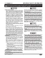
Страница 3: ...EXPLOSION HAZARD Do not store or use gasoline or other flammable vapors or liquids in the vicinity of this or any other appliance Make sure all operators have been instructed on the safe and proper use of the unit WARNING This unit is not intended for use by children or persons with reduced physical sensory or mental capabilities Ensure proper supervision of children and keep them away from the un...

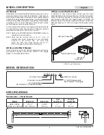
Страница 4: ...to 10ʹ 3 m of element wire leads depending on the installation location of the control box On units with lights the LED wire leads always will be 18 457 mm longer than the element wire leads GR5A and GR5AH Models These models are heat only Controls options are all remote mounted and include a control box ON OFF I O Toggle Switch or an Infinite Heat Control MODEL DESCRIPTION G R 5 A H L XX Glo Ray ...

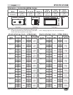
Страница 5: ...450 3 8 12 lbs 5 kg 208 2 2 240 1 9 GR5A 36 120 575 4 8 13 lbs 6 kg 208 2 8 240 2 4 GR5A 42 120 675 5 6 14 lbs 6 kg 208 3 2 240 2 8 GR5A 48 120 800 6 7 15 lbs 7 kg 208 3 8 240 3 3 GR5A 54 120 925 7 7 17 lbs 8 kg 208 4 4 240 3 9 GR5A 60 120 1050 8 8 18 lbs 8 kg 208 5 0 240 4 4 GR5A 66 120 1160 9 7 19 lbs 9 kg 208 5 6 240 4 8 GR5A 72 120 1275 10 6 20 lbs 9 kg 208 6 1 240 5 3 Model Width A Depth B He...

Страница 6: ... 240 6 6 GR5AHL 72 120 1744 14 7 25 lbs 12 kg 208 8 5 240 7 3 Model Voltage Watts Amps Shipping Weight GR5AH 18 120 350 2 9 10 lbs 5 kg 208 1 7 240 1 5 GR5AH 24 120 500 4 2 11 lbs 5 kg 208 2 4 240 2 1 GR5AH 30 120 660 5 5 12 lbs 5 kg 208 3 2 240 2 8 GR5AH 36 120 800 6 7 13 lbs 6 kg 208 3 8 240 3 3 GR5AH 42 120 950 7 9 14 lbs 6 kg 208 4 6 240 4 0 GR5AH 48 120 1100 9 2 15 lbs 7 kg 208 5 3 240 4 6 GR...

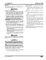
Страница 7: ...al NOTICE Units are voltage specific Refer to specification label for electrical requirements before beginning installation Do not add a decorative soffit to hide a pass through mounted strip heater Excessive heat can cause unit failure Damage to any countertop material caused by heat generated from Hatco equipment is not covered under the Hatco warranty Contact the manufacturer of the countertop ...

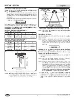
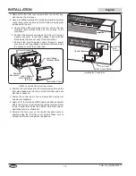
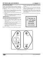
Страница 8: ...ld require the unit to be installed 2 51 mm below the underside of the shelf If minimum distances are not maintained damage to the surroundings and or failure to the unit could occur 2 Fasten the angle brackets to the underside of the shelf using appropriate fasteners not supplied by Hatco Make sure the unit is facing the desired direction with the wire leads on the proper side before fastening th...

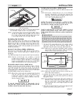
Страница 9: ...ive heat remote mounted control switches must be installed outside the strip heater heat zone Installing the Control Box GR5AL Series Use the following procedure to install the GR5AL Series control box NOTE Units can be ordered with up to 10ʹ 3 m of element wire leads depending on the installation location of the control box The LED wire leads always will be 18 457 mm longer than the element wire ...

Страница 10: ...ge Terminal Block Access Cover Power Knockouts Power Knockouts High Voltage Terminal Block 4 Pole GR5AL Control Box Electrical Connections 6 Position the control box into the cutout opening through the front side Make sure that none of the electrical wires are pinched or stressed 7 Fasten the control box to the vertical surface using four screws not supplied 8 Apply a 1 4 6 mm bead of NSF approved...

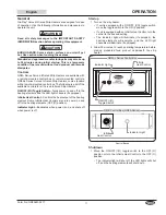
Страница 11: ...ts and the LED light channels if equipped Infinite Heat Control Controls the heat output of the heating element Some Infinite Heat Controls also turn power on and off to the heating elements OFF O position Indicator Light Illuminates when power is on and shuts off when power is off Startup 1 Turn on the strip heater If unit is equipped with a ON OFF I O toggle switch move the toggle switch to the ...

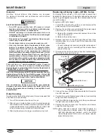
Страница 12: ...t all surfaces be cleaned daily 1 Turn off the unit and allow the unit to cool 2 Wipe down all metal surfaces with a water dampened non abrasive cloth Stubborn stains may be removed with a good stainless steel or non abrasive cleaner Clean hard to reach areas using a small brush and mild soap 3 Wipe dry the entire unit using a non abrasive dry cloth Replacing a Display Light GR5AL Series The displ...

Страница 13: ...nting height if too close Heat control set too high Decrease heat control setting Voltage supply too high Check power supply to unit making sure it matches rating on unit If power supply is incorrect change to match rating Control switches burn out Remote control box is mounted too close to the heat zone Move remote control box away from the heat zone The maximum ambient temperature allowed for th...

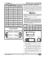
Страница 14: ...asurements c Verify which stand will have the conduit and LED wire leads passing through it and the countertop d Carefully measure locate and tape each template onto the countertop at its appropriate position e Drill holes through the approriate Drill Here locations on each template NOTE Do not drill LED wire hole for GR5A series strip heaters 3 Feed the conduit and LED wire leads from the unit th...

Страница 15: ...sure NOTE RMB Series remote control boxes require one remote control box per strip heater WARNING ELECTRIC SHOCK HAZARD Turn OFF power switch disconnect unit from power source and allow unit to cool before performing any cleaning adjustments or maintenance 1 Determine the area to mount the RMB box IMPORTANT NOTE Remote mounted control boxes and control switches must be installed in a cool dry loca...

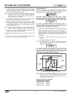
Страница 16: ...plied by a qualified electrician WARNING ELECTRIC SHOCK HAZARD Turn OFF power switch disconnect unit from power source and allow unit to cool before performing any cleaning adjustments or maintenance NOTICE To prevent premature failure of components due to excessive heat remote mounted control switches must be installed outside the strip heater heat zone 1 Verify unit is off and disconnected from ...

Страница 17: ...ENT OR OTHER INTELLECTUAL PROPERTY RIGHT INFRINGEMENT Without limiting the generality of the foregoing SUCH WARRANTIES DO NOT COVER Coated incandescent light bulbs fluorescent lights heat lamp bulbs coated halogen light bulbs halogen heat lamp bulbs xenon light bulbs LED light tubes glass components and fuses Product failure in booster tank fin tube heat exchanger or other water heating equipment ...

Страница 18: ...é et d utilisation fournies dans ce manuel avant d installer et d utiliser l appareil Informations Importantes pour le Propriétaire 18 Introduction 18 Consignes de Sécurité Importantes 19 Description du Modèle 20 Désignation du Modèle 20 Caractéristiques Techniques 20 Dimensions Rampe chauffante 20 Dimensions Boîtier de commande 21 Tableaux des caractéristiques électriques 21 Installation 23 Génér...

Страница 19: ...ION Ne conservez pas ou n utilisez pas d essence ou d autres vapeurs ou liquides inflammables à proximité de cet appareil ou de tout autre appareil AVERTISSEMENT Assurez vous que tous les opérateurs ont été formés à l utilisation sûre et correcte de l appareil Cet appareil ne doit pas être utilisé par des enfants ou des personnes avec des capacités physiques sensorielles ou mentales diminuées Assu...

Страница 20: ... un élément disposant de fils électriques pouvant mesurer jusqu à 3 m 10 en fonction du lieu d installation du boîtier de commande Pour les appareils avec éclairage les fils électriques des LED mesurent toujours 457 mm 18 de plus que les fils électriques de l élément Modèles GR5A et GR5AH Ces modèles produisent de la chaleur uniquement Les options de commande sont toutes montées à distance et comp...

Страница 21: ...208 2 8 240 2 4 GR5A 42 120 675 5 6 14 lbs 6 kg 208 3 2 240 2 8 GR5A 48 120 800 6 7 15 lbs 7 kg 208 3 8 240 3 3 GR5A 54 120 925 7 7 17 lbs 8 kg 208 4 4 240 3 9 GR5A 60 120 1050 8 8 18 lbs 8 kg 208 5 0 240 4 4 GR5A 66 120 1160 9 7 19 lbs 9 kg 208 5 6 240 4 8 GR5A 72 120 1275 10 6 20 lbs 9 kg 208 6 1 240 5 3 Modéle Largeur A Profonduer B Hauteur C Largeur du couvercle D Profondeur du couvercle E Hau...

Страница 22: ...lbs 9 kg 208 8 3 240 7 2 Modéle Tension Amps Intensité Poids d embarquement GR5AHL 18 120 354 3 0 13 lbs 6 kg 208 1 7 240 1 5 GR5AHL 24 120 506 4 3 14 lbs 7 kg 208 2 5 240 2 1 GR5AHL 30 120 668 5 6 15 lbs 7 kg 208 3 2 240 2 8 GR5AHL 36 120 809 6 8 17 lbs 8 kg 208 3 9 240 3 4 GR5AHL 42 120 961 8 1 18 lbs 9 kg 208 4 7 240 4 0 GR5AHL 48 120 1112 9 4 20 lbs 9 kg 208 5 4 240 4 7 GR5AHL 54 120 1264 10 7...

Страница 23: ...ION de ce manuel AVIS Les unités ne fonctionnent qu à la tension spécifiée Reportez vous à l étiquette des caractéristiques des exigences électriques avant de commencer l installation Ne masquez pas une rampe chauffante montée sur un passe plat avec une sous face décorative Une température excessive peut entraîner une panne de l unité Les dommages pouvant être causés au dessus de comptoir par l éq...

Страница 24: ...nécessite un montage 51 mm 2 sous cette dernière Si les distances minimum ne sont pas respectées des dommages à proximité de l appareil et ou un échec de fonctionnement de l appareil pourraient survenir 2 Fixez la cornière sous l étagère en utilisant les fixations adaptées non fournies par Hatco Assurez vous que l appareil est tourné dans la direction souhaitée avec les fils électriques sur le bon...

Страница 25: ...n pour l élément de chauffe et une alimentation faible tension pour la barre à LED suite Étagère Cornière fixée sous l étagère Écart minimum de 25 mm 1 Installation d une étagère plate 3 Orientez les fils électriques de l élément et des barres à LED vers le lieu d installation du boîtier de commande NOTA Les rampes chauffantes arrondies à infrarouge avec éclairage GR5AL Série nécessitent deux sour...

Страница 26: ...e à l intérieur du couvercle du boîtier de commande Borne basse tension Couvercle Entrées défonçables Entrées défonçables Borne haute tension 4 pôles Connexions électriques du boîtier de commande GR5AL 6 Installez le boîtier de commande dans la découpe prévue à cet effet en le faisant passer par l avant Assurez vous qu aucun fil électrique ne soit pincé ou étiré 7 Fixez le boîtier de commande sur ...

Страница 27: ...cule Marche Arrêt I O Allume et éteint les éléments de chauffe et la lumière LED le cas échéant Commande de chaleur continue Régule la sortie de chaleur de l élément de chauffe Certaines commandes de chaleur continue allument ou éteignent également les éléments de chauffe position O Arrêt Témoin lumineux S allume lorsque le courant est allumé s éteint lorsque le courant est éteint Démarrage 1 Allu...

Страница 28: ...ommandé de le nettoyer quotidiennement 1 Éteindre l appareil débrancher le cordon d alimentation et laisser refroidir l appareil 2 Essuyez toutes les surfaces métalliques avec un tissu doux humide Les taches tenaces s enlèvent avec un bon nettoyant non abrasif Nettoyer les zones difficiles d accès avec une petite brosse et du savon doux 3 Essuyez l intégralité de l unité en utilisant un chiffon do...

Страница 29: ...ge est trop élevé Baissez la chaleur La tension est trop élevée Vérifiez l alimentation électrique de l appareil assurez vous qu il correspond aux valeurs sur l appareil Si l alimentation électrique est incorrecte changez pour correspondre aux valeurs Les interrupteurs de commande ont grillé Le boîtier de commande à distance est installé trop près de la zone de chauffe Éloignez le boîtier de comma...

Страница 30: ...l appareil aura les câbles de conduit et de LED passant à travers et sous l étagère d Mesurez déterminez l emplacement et scotchez avec précision chaque patron à l endroit exact sur le comptoir e Percez les trous aux emplacements Percer Ici sur chaque patron NOTA Ne percez pas le trou de câble LED pour les rampes chauffantes des séries GR5A 3 Alimentez le conduit et le câble LED de l appareil à tr...

Страница 31: ...ugmentant la longévité des commandes Tous les modèles sont construits conformément aux standards UL avec des interrupteurs des indicateurs lumineux et des câblages Consultez l usine pour connaître le type et l emplacement des contrôles de la série RMB pour le compartiment NOTA Les boîtiers de commande à distance de la série RMB nécessitent un boîtier de commande à distance par rampe chauffante AVE...

Страница 32: ...teur sous tension allumez l appareil et vérifiez son fonctionnement Commutateur à progression Suivez la procédure suivante pour installer un commutateur à progression Ce commutateur doit être installé par un électricien qualifié dans une boîte un boîtier électrique homologué non fourni AVERTISSEMENT DANGER DE DÉCARGE ÉLECTRIQUE Tournez le interrupteur sur ARRÊT pour éteindre la rampe débranchez le...

Страница 33: ...X DROITS DE LA PROPRIÉTÉ INTELLECTUELLE Sans restreindre la portée générale des énoncés précédents CES GARANTIES NE COUVRENT PAS LES ÉLÉMENTS SUIVANTS ampoules d éclairage à incandescence enduites lumières fluorescentes ampoules de lampes chauffantes ampoules d éclairage à halogène enduites ampoules de lampes chauffantes au xénon tubes d éclairage DEL composants en verre et fusibles défaut de prod...

Страница 34: ...English Form No GR5ALM 0217 34 NOTES ...

Страница 35: ...English Form No GR5ALM 0217 35 NOTES ...

Страница 36: ...ervice St Louis 314 535 2222 NEBRASKA Anderson Electric Omaha 402 341 1414 NEVADA Burney s Commercial Las Vegas 702 736 0006 Hi Tech Commercial Service N Las Vegas 702 649 4616 NEW JERSEY Jay Hill Repair Fairfield 973 575 9145 Service Plus Flanders 973 691 6300 NEW YORK Acme American Repairs Inc Jamaica 718 456 6544 Alpro Service Co Maspeth 718 386 2515 Appliance Installation Buffalo 716 884 7425 ...

Отзывы: