5
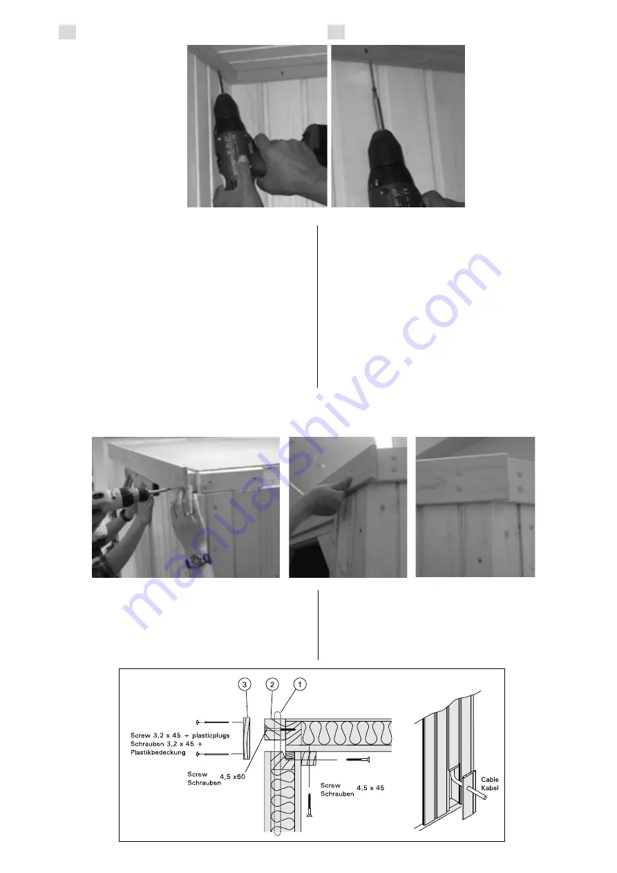
The ceiling strips contain
prefabricated
holes
for
screws. Be sure to drill 3,5
mm holes for the screws
through the panel boards to
prevent them from cracking
upon installation.
The ceiling mouldings should
be screwed first to the walls
so that there is a gap of
approximately 5 mm between
the ceiling and the moulding.
When the screws are screwed
into the ceiling the latter sinks
into the sealing strip that runs
along the top of the walls.
NB! When you are assembling the sauna type EMS1000,
the benches should be positioned inside the sauna itself
by passing them over the walls before the cealing is
actually installed, as they can’t be turned once inside.
The wall contains ready-made electrical installation
tubes for the heater and control unit cables. Their ends
are visible at the top of the element. The exterior wall
contains a detachable panel for the control unit cable,
and there is a similar panel at the bottom of the interior
wall for the heater (Fig. 8). Drill holes for the cable in the
detachable panel if necessary.
A hole for the light fitting cable shall be drilled
diagonally through the upper edge of the wall element
(Fig. 9) or directly through the wall if the cable is
allowed to be visible.
Cable holes for a separate thermostat and any
loudspeakers shall be drilled through the wall or ceiling.
für die Schrauben in die
Täfelbretter, damit sie
beim Anbringen der
Schrauben
nicht
zerbrechen.
Die Deckleiste wird
zuerst an die Wand
geschraubt, und zwar so,
daß zwischen der Decke
und der Leiste eine Spalte
von ca. 5 mm bleibt. Wenn
die Schrauben in die Decke
festgezogen werden, wird
die Decke auf die Dichtung
der Wand sacken.
Achtung! Wenn Sie eine EMS1000-Sauna aufstellen,
sollten Sie, noch bevor Sie die Deckenelemente anbringen,
die Liegen über die Wände in den Saunaraumhieven, weil
sie in der Sauna nicht gedreht werden können.
In der Wand befinden sich bereits installierte Rohre
für die Kabel des Ofens und des Steuergeräts. Ihre
Enden sind oben an der Wand sichtbar. Die Außenwand
enthält ein abnehmbares Element für das Kabel des
Steuergeräts, ein ähnliches Element für das Kabel des
Ofens befindet sich unten an der Innenwand (Abb. 8).
Bohren Sie in das abnehmbare Element bei Bedarf einen
Durchlass für das Kabel.
Die Öffnung für das Lampenanschlusskabel muss
diagonal durch den oberen Rand des Wandelements
(Abb. 9) oder direkt durch die Wand gebohrt werden,
falls das Kabel sichtbar sein darf.
Es wird geraten, Öffnungen für die Kabel eines
separaten Thermostats oder von Lautsprechern durch
die Wand oder die Decke zu bohren.
Figure 8.
Abbildung 8.
EN
DE
Figure 7.
Abbildung 7.
Assembling the Fascia Boards
Before assembling the fascia boards (15 x 90 ) (3) ensure
that all electrical cables belonging to the heater and the
lamp have been fitted and connected correctly. Use 4,5
x 60 mm screw s w hen fastening the filling battens (2)
under the fascia boards at distances of 500 to 600 mm.
The outermost battens need to be as close as possible to
the corner.
Saw the
f a s c i a
boards (3)
to the right
length and
use 3,2 x 45
mm screw s
to
fasten
them
in
place.
Montage der Blendleisten
Stellen Sie vor der Montage der Blenden (15 x 90) (3) sicher,
daß die Elektrokabel des Ofens und der Beleuchtung richtig
vergelegt und angeschlossen sind. Unter den Blenden
w erden Kanthölzer (2) im Abstand von 500 mm bis 600
mm mit 4,5 x 60 mm Schrauben montiert. Die äußersten
Kanthölzer sollten möglichst ecknah placiert w erden.
Sägen Sie die
Blendleist en
(3) auf die
richtige Länge
und nageln Sie
sie mit den 3,2
x
45
mm
Schraube fest.
Figure 6.
Abbildung 6.
Содержание VARIANT
Страница 10: ...10 Ceiling Dach Ceiling Dach EMS1000 EMS1500 ...
Страница 11: ...11 Ceiling Dach EMS2000 ...


