ENVI
®
Control
16
1.6.2.3
CH Mode 2 (Outdoor Control
)
Outdoor Sensor required.
A list of accessory choices for different applications is shown in section 1.0 on page
3.
Description
In this mode, setpoint is varied by the outdoor air temperature (ODA). Upon enabling the boiler, the ENVI
®
control
fires and modulates the boiler to maintain outlet water temperature at the setpoint determined by the outdoor air
temperature and its settings. The upper (HYSTERESIS OFF) and lower (HYSTERESIS ON) temperature differentials
control the temperature at which the burner turns on or off.
Notes:
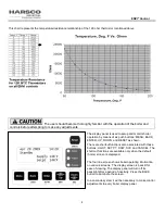
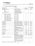
Reference table and graph in section 1.6.2.2 for example of ODA to Boiler Temp relationship.
NOTE:
The boiler is enabled when the temperature of the outdoor sensor drops below the ODA
SHUTDOWN temperature that can be changed within the CH settings.
The TB-1/LV terminals 1 and 2 (enable/disable) operate the switching on/off of the night setback function.
The night setback setpoint is set within CH settings and reduces the CH set point by its value while
enabled. (TB-1/LV terminals 1 and 2 circuit closed)
1.6.2.4 CH Mode 3 (Setpoint Control)
Description
In this mode, the boiler functions as described in 1.6.2.1,
CH Mode
0, except that the external thermostat does not
create the call for heat. The closure of TB1/LV terminals 1 and 2 will reduce the CH setpoint by the value of the night
setback setting.
Example
: Using the values, CH SP=180° F and Night Setback=10° F, when TB1/LV terminals 1 and 2 are open the
CH setpoint will be 180° F. When TB1/LV terminals 1 and 2 are closed the CH setpoint will be 170° F (180° F -10° F).
NOTE:
In this mode the boiler will always run to setpoint, since there is no enable circuit closure required.
The TB-1/LV terminals 1 and 2 (enable/disable) operate the switching on/off of the night setback function.
The night setback setpoint is set within CH settings and reduces the CH set point by its value while
enabled. (TB-1/LV terminals 1 and 2 circuit closed)
1.6.2.5 CH Mode 4 (Header & Stat)
This mode is preferred for the master boiler in a cascade system.
A sensor will be needed to sense header temperature. A list of accessory choices for different applications is shown in
section 1.0 on page 3.
Description
In this mode, the boiler functions as described in 1.6.3.1,
CH Mode 0
, except that the boiler maintains the setpoint
temperature where the header sensor is located.
NOTE:
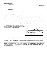
The boiler is enabled by the TB1/LV terminals 1 and 2 (enable/disable) becoming closed or
shorted.
This circuit is energized internally.
DO NOT APPLY EXTERNAL POWER TO THESE
TERMINALS.
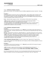
Note: Placing the master boiler in CH mode 4 on any cascade application will show the header temperature (HDR
Supply) on the display in the place of the supply temperature on the third line of text on the master boiler.

