ENVI
®
Control
26
ENVI
®
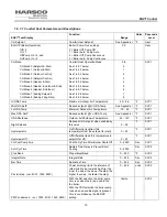
Text Display
Function
Range
Units
Pass code
Level
Quic Start Tme
See Below 1.8.4.8.13
1
– 255
Sec
SVC2
Hys Quick Stop
See Below 1.8.4.8.13
0
– 51
°F
SVC2
Quic Stop Time
See Below 1.8.4.8.13
1
– 255
Sec
SVC2
LoLoad Waiting
See Below 1.8.4.8.14
0
– 255
Sec
SVC2
Start Rotation
(ver. 112E, BD71, 49A7, 79F2,
8C51)
(ver. 1043, 9820)
See Below 1.8.4.8.15
Off
On:1-255
On:1-255
Hours
Days
SVC2
No Blr on Wait
See Below 1.8.4.8.16
1
– 255
Min
SVC2
Anti wind up
See Below 1.8.4.8.17
On/off
SVC2
Lead boiler
(ver. 1043, 9820)
See Below 1.8.4.8.18
0 - 23
SVC2
1.8.4
Master Modes (a more detailed description of Power Modes can be found in section 1.8.5.1.1)
1.8.4.1
Power mode = 0, Min Boilers on (typically not the most efficient of the two power mode options)
In this mode, when more than two boilers are required to satisfy the load, the last two boilers on will run to 100%
as needed. All other boilers will modulate in parallel. This satisfies the load with the minimum amount of boilers
firing (Less efficient operation).
Example: BLR 1 on 100%, BLR 2 on 100%, as BLR 3 comes on BLR 1 will begin to modulate as BLR 3 runs to
100% when BLR 4 comes on and runs to 100%, BLR 2 will begin to modulate. This sequence will continue until the
demand is satisfied. The staging procedure is first on, last off.
Power mode = 1, Max Boilers On (Parallel Modulation – Default Setting)
In this mode, the boilers modulate in parallel based on a signal from the master boiler. This satisfies the load with
the necessary number of boilers firing at the lowest fire rate possible resulting in more efficient operation in most
cases.
The staging procedure is first on, last off.
1.8.4.2
Header Mode = 0, (Header & Stat)
Sensor kit required to sense header temperature. A list of accessory choices for different applications is shown in
section 1.0 on page 3.
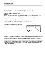
In this mode, the master boiler controls the operation of all the boilers in the cascade system to maintain a supply
temperature where the header sensor is located. Upon an enable signal, from the closure between terminals
TB1-1 & TB1-2, the ENVI
®
control on the Master boiler fires and modulates the boilers to maintain header water
temperature at the header setpoint. The upper (HYST STOP BLR) and lower (HYST START BLR) temperature
differentials in conjunction with other cascade settings control the header temperature at which boilers are added
or removed.
Example: The Master boiler operates the system to maintain the header setpoint of 160° F. If the temperature
increases above 170° F (setpoint 160° F + 10°F HYST STOP BLR), a boiler will shut off. If the temperature
decreases below 151°F (setpoint 160°F
– 9°F HYST START BLR), another boiler will start.
NOTE:
The cascade system is enabled by the TB1/LV terminals 1 and 2 (enable/disable) on the master boiler
becoming closed or shorted.
This circuit is energized internally.
DO NOT APPLY EXTERNAL POWER TO THESE TERMINALS.


