


Operation
OTM-20 Installation and Operation Handbook
3-2
GUI
LCD Contrast
After powering on, the Graphical User Interface (GUI) will be displayed, as shown in
Figure 3-2
.
Figure 3-2. Boot-up GUI of Optical Test Meter
The surrounding temperature will affect the LCD contrast. Contrast can be adjusted by
pressing the
button through the following procedures.
•
Power on the instrument, the GUI is displayed (as shown in Figure 3-2).
•
Press the
button and the contrast will be increased. Press
button and the
contrast will be reduced.
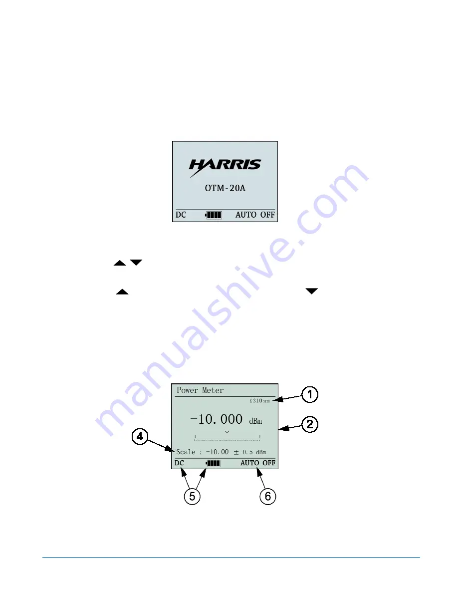
Power Meter and Laser Source Interface
Press
FUNC
and the instrument will enter the Power Meter interface, as shown in
Figure 3-3
.
Figure 3-3. Power Meter Interface
Press
FUNC
again to switch between the Power Meter interface and the Laser Source
interface. The Laser Source interface is shown in
Figure 3-4
.
Содержание OTM-20
Страница 5: ...OTM 20 Installation and Operation Handbook Figure 2 WEEE Compliance Symbol...
Страница 6: ...OTM 20 Installation and Operation Handbook Blank Page...
Страница 10: ...Contents OTM 20 Installation and Operation Handbook iv Blank Page...
Страница 36: ...Operation OTM 20 Installation and Operation Handbook 3 20 Figure 3 33 Set Default Confirmation GUI...
Страница 44: ...Data Collection Software OTM 20 Installation and Operation Handbook 4 8 Blank Page...


