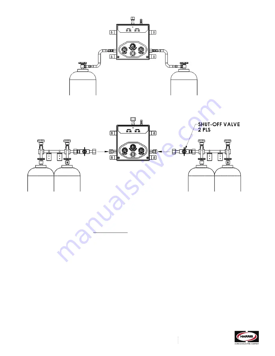
Figure 4
6. Align the right and left header bar with the right and left inlet connections to the box. See Figure 5 for an illustration of this. Make sure that the header bars are level and
perpendicular to the box. Attach the header mounting brackets to the wall with appropriate hardware (not included). Assemble the header outlet connection to the control box
on both the right and left side. Wrench-tighten all connections. Tighten the U-bolts on the header mounting brackets to secure the headers in place.
Figure 5
7. Attach the hoses to the header valves and wrench tighten.
8. Attach the other end of the hose to the cylinder and wrench tighten. Each hose has a gas specific CGA connection with a non-return valve on the end that attaches to the cylinder.
Insure that the flow direction arrow on the CGA connection is pointed in the proper direction of gas flow (toward the header bar). Otherwise, gas will not flow through the hose
when the cylinder valve is opened.
9. Operation Instructions
NOTE: A detailed operational video can be viewed at -
http://bit.ly/Tz1JYd
Once the control box and headers and/or hoses have been properly installed, the system is now ready to put into operation. Caution: Be sure all connections are wrench tight
before proceeding to operate the system.
1. Remove the front cover of the manifold control box with a Phillips Head screwdriver.
2. Using a 5/32” Allen Hex Key, loosen or remove the set screw of the top delivery pressure regulator. This regulator will be reset to the desired pressure later.
3. If equipped, close the master shut off valves for both the right and left side. Refer to Figure 5 for the location of the master shut off valves.
4. Turn the selector knob on the control box to the primary side (right or left).
5. S-L-O-W-L-Y open the first cylinder valve on the primary side. Warning: It is important that all cylinder valves be opened slowly to minimize the heat of recompression, which
can create hazardous situations with high pressure oxidizing gases.
6. Check for leaks at both ends of the hose; at the cylinder and also at the header bar . Use a soapy water solution or any oxygen compatible commercial leak detector to check
for leaks. If leaks are found, they must be eliminated before proceeding. Attempt to re-tighten connections with a wrench until the leakage stops. If leakage cannot be stopped,
do not use the manifold. Contact The Harris Products Group, or, your local gas supplier.
7. Once all leaks are eliminated, proceed to open up all cylinders on the primary side repeating steps 5 and 6 for each one.
8. Proceed to open up all cylinders on the reserve or secondary side repeating steps 5 and 6 for each one.
9. If equipped, S-L-O-W-L-Y open the master shut off valve on the primary side and check for leaks where the header bar attaches to the control box using soapy water or
commercial leak detector as in step 6. Eliminate any leaks found.
10. Repeat step 7 for the reserve or secondary side.
11. Check to insure that both the RIGHT BANK gauge and LEFT BANK gauge read the proper pressure from the cylinders.
12. With the right bank and left bank now open, and the primary knob turned to indicate the primary bank, adjust the delivery pressure to achieve the desired pipeline pressure
using the 5/32” Allen Hex Key. Rotate the adjusting screw clockwise until the desired pressure is read on the delivery pressure gauge. It may take a few seconds for the
pressure to equalize in the downstream pipeline.
THE HARRIS PRODUCTS GROUP
www.harrisproductsgroup.com
1.800.241.0804


