1056748 03/2023
1056748 03/2023
69
68
Assembly
7.2.4 General installation instructions
It should be noted that the machine is generally exposed to a higher noise level in an industrial environment than in
laboratory operation. To ensure stable operation, the following wiring and installation instructions must be observed:
A good grounding concept for the machine or system is the basic requirement for trouble free operation. In addition
to the protective earth conductors with the specified cross-sections, a good grounding also includes low-impedance
earthing in the high-frequency range (HF). Low impedance HF earthing can be achieved with a large area earth
connection, for example by using earthed machine parts. A large area cable duct made of sheet metal, for example, has
a much lower impedance in the HF range than a protective earth conductor. At transition points such as joints or hinges,
the use of earthing strips made of flat stranded wires offers significantly better earthing of high-frequency interference
than the use of round earthing stranded wires.
Shielded motor and encoder cables must be used! Make the unshielded open motor strands on the controller as short
as possible. Never cut or interrupt the shielding on encoder cables. Poor shielding of the encoder cable will inevitably
lead to jerking of the motor or to a controller shutdown. Depending on the servocontroller used, an encoder error can be
detected.
As the motor current increases, so does the interference potential on the power path. Power cables and encoder cables
should therefore generally be routed as separately as possible. This is often only possible to a limited extent if these
cables are routed in drag chains, for example.
Signal and power cables should also not be crossed. If a crossing of signal and power cables is unavoidable, they
should be carried out at right angles to each other if possible.
7.2.5 Commutation setting
For accurate position setting, the servo motor and its control device are fitted with a measuring device (feedback); which
determines the current position (e.g., the angle of rotation set for a starting position) of the motor. This measurement is
affected via a rotary encoder, e.g., a resolver, an incremental encoder or an absolute encoder. The position controller
compares the signal from this encoder with the pre set position value. If there is any deviation, then the motor is turned
in the direction which represents a shorter path to the set value which leads to the deviation being reduced. The
procedure repeats itself until the value lies incrementally or approximately within the tolerance limits. Alternatively, the
motor position can also be digitally recorded and compared by computer to set a value. Servo motors and actuators
from Harmonic Drive SE use various motor feedback systems which are used as position transducers to fulfil several
requirements.
Commutation:
Commutation signals or absolute position values provide the necessary information about the rotor position to ensure
correct commutation.
During initial commissioning, the commutation offset must be determined by the drive controller.
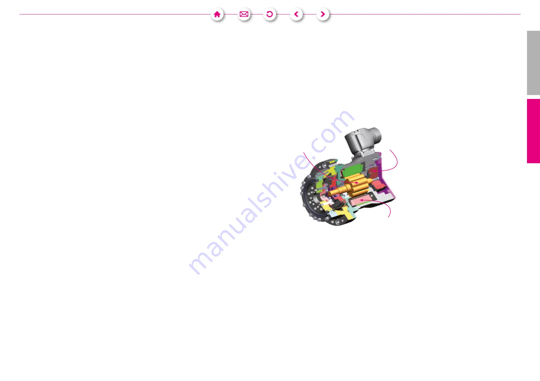
Stator
Rotor magnet
Motor feedback
Speed actual value:
The actual value signal required for speed control is obtained in the servo controller from the cyclical change in position
information.
Position actual value:
Incremental encoder: The actual value signal required for position control is formed by adding up incremental position
changes. For incremental encoders with square wave signals, the resolution can be quadrupled through edge evaluation
(quadcounting). For incremental encoders with SIN/COS signals, the resolution can be increased by interpolation in the
controller.
Absolute encoder:
Absolute encoders provide absolute position information over one (singleturn) or several (multi-turn) revolutions. On
the one hand, this information can be used to determine the rotor position for commutation, and on the other hand,
a reference run can be omitted if necessary. In the case of absolute encoders with additional incremental signals, the
absolute position information is typically read out during switch-on, after which the incremental signals are evaluated to
form the actual speed and position values. Fully digital absolute encoders as motor feedback systems have such a high
resolution of the absolute value that additional incremental signals are not required.
Deutsch
English
Assembly Instructions Servo Actuators


