10
| www.harmar.com | 800-833-0478
TEC0029 2016SEPT12 PN: 630-00001 REV C
Installation Procedures
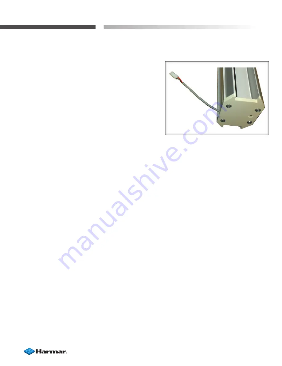
19. Plug in the power supply.
The top and bottom of
the rail each have a short wire and plug coming from
the rail end. Plug the power supply into one of these
plugs and plug the other end of the power supply into
a wall outlet. You may use whichever end is a more
convenient location to a wall outlet.
[Figure 10-1]
20. Turn on the main power breaker on the chassis.
The status LED indicator will cycle from RED to AMBER
to GREEN to OFF, and then the lift will emit a beep. The
indicator should then return to GREEN, indicating the
lift is now ready to run.
If the indicator does not return to GREEN, check the
following:
• AMBER:
Indicates an obstruction. Five
obstruction sensors include: uphill chassis,
downhill chassis, uphill ramp, downhill ramp, and
platform safety pan. Check them all to ensure that
one (or more) is not triggered and check all these
wiring connections.
• RED:
Indicates a fault or double obstruction. If
two or more obstruction sensors are triggered
at the same time the lift will disable itself. Turn
the main power breaker off, wait a couple of
seconds and then turn the breaker back on.
If the lift is on the final limit it is also treated
as a fault and the lift will have to be hand
cranked off the limit. To do this, run the lift up
to the top landing until the lift stops. When
the lift stops, the ramp motor will turn on
to lower the ramp. If you release the rocker
switch the ramp will stop; continue holding
the rocker switch until the ramp stops on its
own. It may be necessary to slide the upper
limit cam down to get the lift to stop at the
proper place in relation to the landing.
Figure 10-1


