background image

Harman®  •  P43 Installation Manual_R23  •  2008 -___  •  04/14

16

3-90-04301i

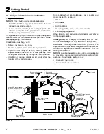
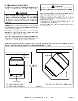
Outside air flex 

pipe goes here.

Outside Air:

Hearth & Home Technologies recommend attaching 

outside air in all installations, especially lower level and 

main floor locations.

Per national building codes, consideration must be given to 

combustion air supply to all combustion appliances. Failure 

to supply adequate combustion air for all appliance demands, 

may lead to back-drafting of those and other appliances. 
When the appliance is side-wall vented: The air intake is best 

located on the same exterior wall as the exhaust vent outlet 

and located lower on the wall than the exhaust vent outlet.
When the appliance is roof vented: The air intake is best 

located on the exterior wall oriented towards the prevailing 

wind direction during the heating season.
The outside air connection will supply the demands of the 

pellet  appliance,  but  consideration  must  be  given  to  the 

total house demand. House demand may consume some 

air needed for the stove, especially during a power failure. It 

may be necessary to add additional ventilation to the space in 

which the pellet appliance is located. Consult with your local 

HVAC professional to determine the ventilation demands for 

your house. 
To install outside air use 3". non-combustible flex pipe Figure 

4.13. There is a break-away hole on the rear panel of the 

P43 stove which must be removed before connecting the 

flex pipe. Figure 4.12. The pipe should be run outside and 

terminate to the side or below the vent pipe outlet so the flue 

outlet is more than 12" from the inlet cover. The Termination 

Cap should be used to keep birds, rodents, etc. out of the 

pipe Figure 4.13.
You may choose to use the optional Direct Vent Wall Pass-

through Kit which incorporates the venting pass-through and 

outside air inlet into one component. Figure 4.14. 

Direct Vent Wall Pass-through Kit 

(Part #1-00-677177)

D. Outside Air

Figure 4.12

Figure 4.14

Termination Cap 

part# 1-10-09542

Figure 4.13

Содержание P43

Страница 1: ...with local regional state and national codes and regulations Contact local building or fire officials about restrictions and installation inspection requirements in your area Tested and approved for...

Страница 2: ...tions 4 E Non Combustible Materials Specification 4 F Combustible Materials Specification 4 G Electrical Codes 4 2 Getting Started A Design and Installation Considerations 5 B Tools and Supplies Neede...

Страница 3: ...l roof flashing installed and sealed ________________________________ Terminations installed and sealed ________________________________ Electrical Section 1 Pg 4 120VAC unswitched power provided to t...

Страница 4: ...will be voided by the below actions DO NOT Install or operate damaged appliance Modify appliance Install other than as instructed by Hearth Home Technologies Operate the appliance without fully assemb...

Страница 5: ...vent termination CAUTION If burning shelled field corn you must use approved venting specifically designed for corn to prevent corrosion or degradation Follow the instructions from the venting manufa...

Страница 6: ...installation Follow these instructions carefully during the installation to ensure maximum safety and benefit WARNING Risk of Fire or Explosion Damaged parts could impair safe operation DO NOT instal...

Страница 7: ...n Manual_R23 2008 ___ 04 14 7 3 90 04301i 20 3 4 22 10 33 1 2 5 1 8 13 3 4 28 5 16 3 Clearances Figure 3 1 A Appliance Dimension Diagram Dimensions are actual appliance dimensions Use for reference on...

Страница 8: ...to consider the required clearances to walls see Figure 3 2 Figure 3 2 10 254mm with side shields 16 406mm without side shields 2 51mm 36 914mm 10 254mm 16 406mm 9 228mm With or Without Side Shields...

Страница 9: ...e pipe The minimum floor protector material is 20 gauge sheet metal Other floor protector materials are ceramic tile stone brick etc Figure 3 3 NOTE for Canadian installation only Per ULC S627 00 If i...

Страница 10: ...wall pass through 2 Preferred method Figure 4 2 This method also provides excellent venting for normal operation but requires the stove to be installed farther from the wall The vertical portion of t...

Страница 11: ...ting fireplace chimney Figure 4 4 This method provides excellent venting for normal operation This method also provides natural draft in the event of a power failure If the chimney condition is questi...

Страница 12: ...ent pipe fittings Seal pipe joints with silicone or aluminum tape in addition to the sealing system used by the manufacturer Pipe size should be increased to 4 using this method 6 Installing into an e...

Страница 13: ...ed by the manufacturer Note Do not place joints within wall pass through Figure 4 7 Figure 4 8 Figure 4 9 Area within dotted circle represents the minimum clearance to combustible materials such as sh...

Страница 14: ...is fully open on a minimum of 2 sides beneath the floor NOTE Where passage through a wall or partition of combustible construction is desired the installation shall conform to CAN CSA B365 if in Canad...

Страница 15: ...ical from the flue stub may require more frequent cleaning due to fly ash falling off inside and collecting directly above the combustion blower outlet Any use of horizontal venting will require more...

Страница 16: ...liance but consideration must be given to the total house demand House demand may consume some air needed for the stove especially during a power failure It may be necessary to add additional ventilat...

Страница 17: ...he flue pipe connect a draft meter The draft meter must have a minimum range of 0 5 Record the first reading Connect flue pipe to stove and be sure all doors and windows in the home are closed Record...

Страница 18: ...mends Installing the pellet vent with a minimum vertical run of five feet preferably terminating above the roof line Installing the outside air intake at least four feet below the vent termination To...

Страница 19: ...tend with small fires In the event of a hopper fire Evacuate the house immediately Notify fire department J Inspect Appliance Components Remove appliance and components from packaging and inspect for...

Страница 20: ...l sides of the burn pot and that the back of the guide rests against the body of the stove Figure 5 3 INSTALL EXHAUST VENT AT CLEARANCES SPECIFIED BY THE MANUFACTURER Most pellet vent pipe requires a...

Страница 21: ...nt should be done by the installer during set up because a draft meter reading is required to insure proper set up Combustion Motor Speed Control Low draft only set point The small straight screwdrive...

Страница 22: ...stove and could result in a House fire Use only approved fuels and operation guidelines The stove is hot while in operation Keep children clothing and furniture away Contact may cause skin burns CAUT...

Страница 23: ...ONTACTS N O MALE FEMALE CONNECTIONS BONDED TO STOVE BODY GREEN WIRE IS GROUND P O W E R C O R D 1 8 3 R U B B E R C O R D WHITE GREEN BLUE GREEN WHITE RED MALE FEMALE CONNECTIONS BROWN WHITE MALE FEMA...

Страница 24: ...U S A Copyright 2012 Harman a brand of Hearth Home Technologies Inc 352 Mountain House Road Halifax PA 17032 www harmanstoves com Please contact your Harman dealer with any questions or concerns For t...

Отзывы: