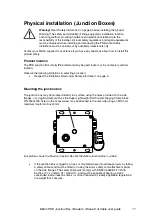
Martin PDE Junction Box / Break-In / Break-Out Cable user guide
17
Data connection to Passive Junction Box or Break-In Cable using DMX512
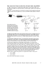
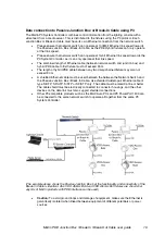
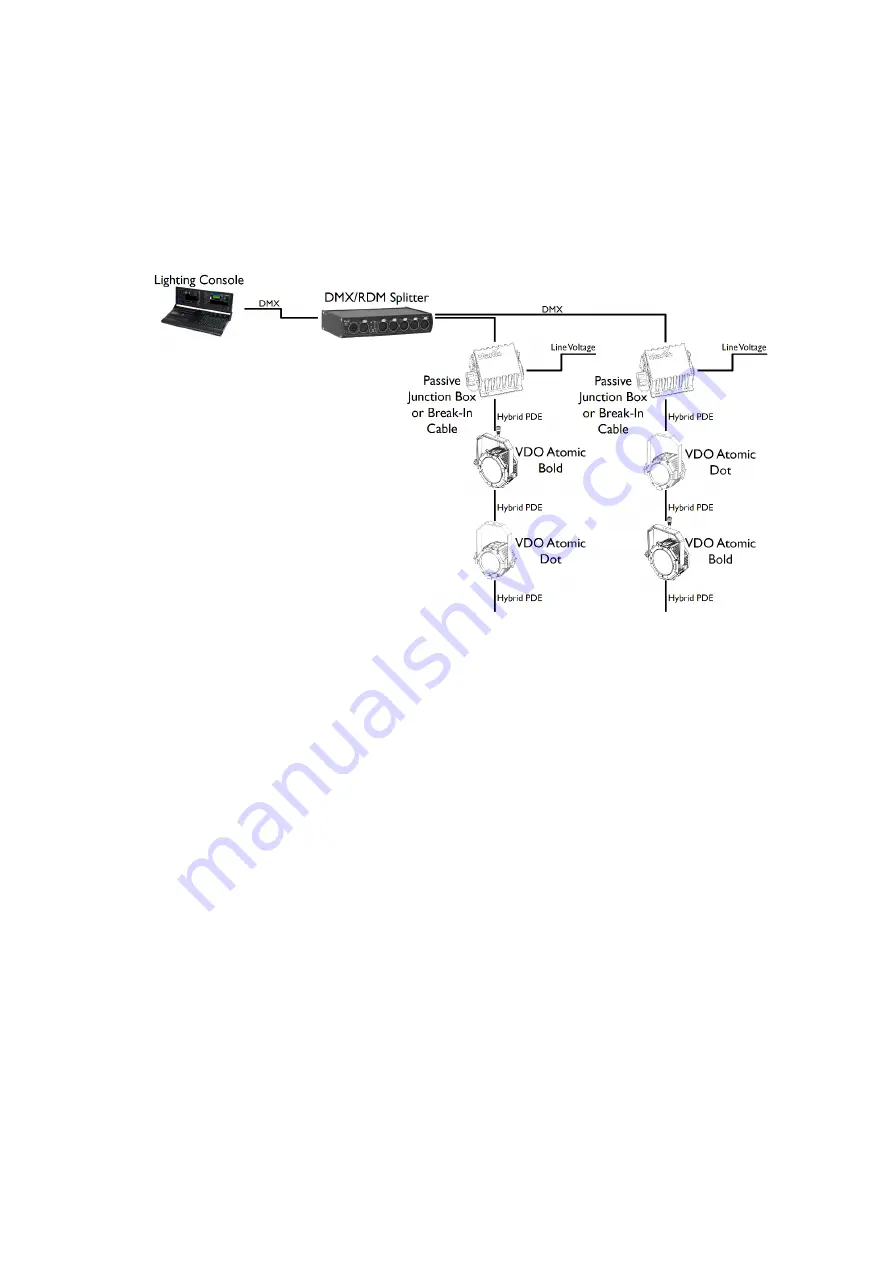
In a DMX-controlled system, an RDM-compliant DMX lighting controller sends a DMX control
data signal over a DMX link to the junction boxes or break-in cables, and then over the hybrid link
to the fixtures.
A DMX pass – through connector is not provided. If you need to connect multiple Junction Boxes
or Break-In cables to the same DMX line, you must use an RDM-compliant splitter as described
below.
The DMX link requires DMX cable. It can be maximum 300 m (1000 ft.) in length and must run in
one single daisy-chain, but it can be extended or split into branches using an RDM-compliant
amplifier/splitter. Alternatively, you can run the DMX signal from the controller over Ethernet
cable using Art-Net protocol and convert it to a DMX-compliant signal with an Art-Net to DMX
converter.
For reliable DMX and RDM data transfer, it is recommended to terminate each branch with a
termination plug – this contains a 120 ohm resistor between the cold and hot DMX data lines
(pins 2 and 3 on XLR5, pins 4 and 7 on PDE connector). This means that the female PDE
connector of the last fixture on a chain need to be fitted with such a termination plug.
The total length of DMX cable and Hybrid PDE cable combined must not exceed 300 m
(measured between lighting console, DMX node or DMX splitter and last fixture on the chain).
If you would like assistance with creating a DMX link, your Martin® supplier will be glad to advise.
The number of fixtures that you can control on one DMX link is limited by the number of DMX
channels each fixture will use and the 512 DMX channels available in one DMX universe at the
DMX controller. Each time you have used 512 channels, you must create a new DMX link that is
connected to a new DMX universe on the controller. Note that this limit applies to the
DMX link
.
The maximum safety limits that apply to the chain of fixtures and cable (see “Safety limits for
connecting devices” on page 12) take priority and must be respected in all cases.
DMX512 data is connected to the junction box using the XLR5 connector. The pin-out is:
x
pin 1 = shield
x
pin 2 = cold (-)
x
pin 3 = hot (+).
Pins 4 and 5 in the XLR connectors are not used.
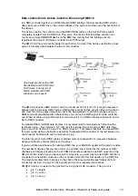
(this example shows the
Passive Junction Box, but the
functionality and connectivity of
the Break-In Cable is identical.
Also VDO Atomic Bold and VDO
Atomic Dot fixtures are shown,
but any mix of Martin products
with PDE interface can be used)

