pg. 15
…MU-1300 specifications continued
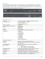
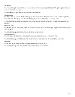
P1 / P2 LED
Programmable LEDs available to control scripts
Serial TX / RX LED
Activity LEDs for each port in each direction. Blinks on activity.
IR TX LED
Activity LEDs for the IR/Serial port. Blinks on transmission.
I/O LED
LED indication of I/O Status. On for digital input or output active
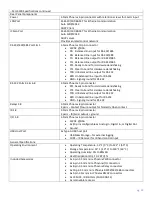
Rear Panel Components
Power
3.5mm Phoenix 2-pin connector with retention screws for 12vdc input
LAN Port
RJ-45 10/100 BASE-T for Ethernet communication
Auto MDI/MDI-X
DHCP Client
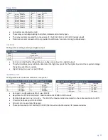
Serial Port 2
3.5mm Phoenix 5-pin connector. RS232 with hardware handshaking
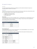
20 pin double stack Phoenix connector
All remaining device control connections:
•
Lower 10 pins – RS-232/422/485 plus hw hands power
•
Upper Left 6 pins – 4 Input/Output plus Ground and Power
•
Upper Right 4 pins – 2x IR/Serial output ports
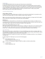
USB Host Port
2x Type-A USB host port
•
USB Mass Storage – for external logging
•
FLIRC – IR Receiver for IR hand control input
General Specifications:
Operating Environment
•
Operating Temperature: 32° F (0° C) to 122° F (50° C)
•
Storage Temperature: 14° F (-10° C) to 140° F (60° C)
•
Operating Humidity: 5% to 85% RH
•
Heat Dissipation (On): 10.2 BTU/hr
Included Accessories
•
1x 2-pin 3.5 mm mini-Phoenix PWR connector
•
1x 6-pin 3.5 mm mini-Phoenix I/O connector
•
1x 10-pin 3.5mm mini-Phoenix RS232/422/485 connector
•
1x 5-pin 3.5mm mini-Phoenix RS232 connector
•
1x CC-NIRC, IR Emitters (FG10-000-11)


