background image

Configuration

14

MXA-MP & MXA-MPL Instruction Manual

Configuration

Overview

To use the MXA-MP or MXA-MPL, the Modero X Series touch panel to which it is connected needs to be configured to receive its 

signals. This is done through the touch panel’s 

Settings

 pages.

NOTE: 

For more information on accessing a Modero X Series touch panel’s Settings Pages, please refer to the 

Modero X Series 

Programming Guide

, available at www.amx.com.

To configure the touch panel:
1.

From the 

Settings

 page, select 

Connections & Networks

.

2.

From the 

Connections & Networks

 page, select 

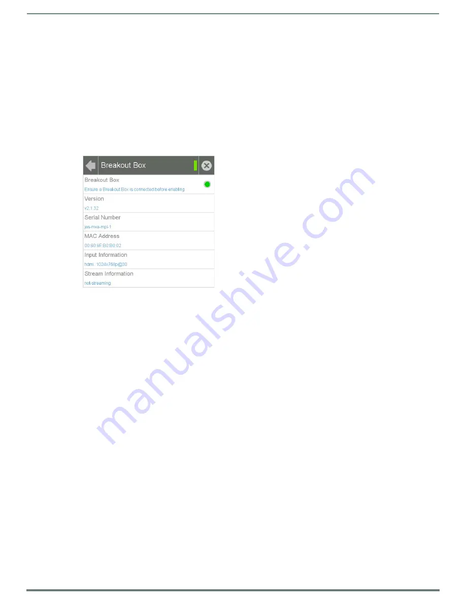
Breakout Box

 to open the 

Breakout Box

 page (FIG. 8).

3.

Press the 

Breakout Box

 button to enable the panel to receive information from the device. 

4.

If the device is connected, the remaining information on the 

Breakout Box

 page will self-populate as the touch panel receives 

that information from the device.

NOTE: 

If the device is not connected to the touch panel at this time, any attempts at enabling the panel will fail, and the 

Breakout Box

 page will be blank other than the Breakout Box button.

5.

The touch panel will now display images or video from the device.

Uploading MXA-MP and MXA-MPL Firmware

Firmware updates and upgrades for the MXA-MP and MXA-MPL must be done through NetLinx Studio.

NOTE: 

Verify you are using the latest NetLinx Master and Modero firmware, as well as the latest version of NetLinx Studio and 

TPDesign 4. Configuring the MXA-MP or MXA-MPL in NetLinx Studio requires at least version 3.3, available at www.amx.com.

To upload new firmware to the MXA-MP and MXA-MPL:
1.

Connect the MXA-MP or MXA-MPL to the intended Modero X Series touch panel and network. For more information on the 

connection, please refer to the 

Installation

section on page 10.

2.

Once the Modero X Series panel is booted and connected to the device, select the appropriate method for Master connection.

3.

Ensure that the device is visible to the Modero X Series panel. The 

Status

 LED on the device (FIG. 1) should toggle on and off 

every 5 seconds.

4.

Ensure the 

Reboot Device

 button is checked in NetLinx Studio.

5.

Locate and download the latest firmware update at 

www.amx.com

.

6.

Begin the upgrade by downloading the file.

7.

After the transfer, the panel and the device will reboot and perform the firmware upgrade. After the upgrade, the device 

contains the latest firmware release.

NOTE: 

The device will not be ready for use and will not show up on the online tree in NetLinx Studio until AFTER its 

Status

 LED begins 

to blink again.

FIG. 8  

Breakout Box Settings page

Содержание AMX Modero X Series

Страница 1: ...INSTRUCTION MANUAL MODERO X SERIES MULTI PREVIEW AND MULTI PREVIEW LIVE MXA MP MXA MPL ...

Страница 2: ...and the point where they exit from the apparatus 11 ONLY USE attachments accessories specified by the manufacturer 12 USE ONLY with a cart stand tripod bracket or table specified by the manufacturer or sold with the apparatus When a cart is used use caution when moving the cart apparatus combination to avoid injury from tip over 13 UNPLUG this apparatus during lightning storms or when unused for l...

Страница 3: ...ote About Wall and Rack Installation 12 Installation Recommendations 13 Rack Mounting the MXA MP MPL 13 Configuration 14 Overview 14 Uploading MXA MP and MXA MPL Firmware 14 Programming the MXA MP and MXA MPL Output 15 Best Practices 15 Resetting the MXA MP MPL s Configuration to Factory Defaults 15 Resetting the MXA MP MPL s Firmware to Factory Defaults 15 MXA MPL Latency 15 NetLinx Programming 1...

Страница 4: ...Table of Contents 4 MXA MP MXA MPL Instruction Manual Appendix Video Streaming Troubleshooting 21 Optimizing Motion JPEG Video Presentation and Speed 21 Transcoding Guidelines 21 ...

Страница 5: ...o X Series Touch Panel Multi format video input accepts HDMI and DVI Seamlessly interconnects between a Modero X Series Touch Panel and an Enova DGX or Enova DVX NOTE The MXA MPL supports the delivery of HDMI 1 4a w HDCP content to a Modero X Series touch panel The MXA MPL has a HDMI input and delivers that video content to the Modero X Series panel over a dedicated link using a proprietary interf...

Страница 6: ...port RJ 45 connector with Ethernet IP pass through AUDIO Audio Input Unbalanced 1 8th inch mini jack connector for use with non HDMI audio only FRONT PANEL COMPONENTS Power 1 LED green lights when device is receiving power Status 1 LED toggles on off green every 5 seconds if communicating to the panel i e the panel is configured to use the MXA MPL Video Input 1 LED red lights when receiving video ...

Страница 7: ...1RU 7 3 Depth FG5968 30 AC SMB Surface Mount Bracket Accessory FG525 CC DVI 5BNCM DVI to 5 BNC Male Cable 6 FG10 2170 08 CC DVI RCA3M DVI to 3 RCA Male Cable 6 FG10 2170 09 CC DVIM VGAF DVI to HD 15 Female Adapter FG10 2170 13 CC DVI SVID DVI to S Video Cable FG10 2170 10 CC 3 5ST5 RCA2F 5 pin 3 5mm Phoenix style to 2 RCA Female Cable FG10 003 20 ...

Страница 8: ...ts HDMI sources into video snapshots Easily add to existing implementations that use an Enova DGX or Enova DVX with a Modero X Series Touch Panel Product Specifications FIG 2 MXA MP MXA MP Specifications DIMENSIONS HWD 1 9 16 x 8 1 4 7 3 16 4 cm x 21 cm x 18 2 cm WEIGHT 2 80 lbs 1 27 kg POWER IEC power cord connector 100 240 VAC 47 63 Hz Power Consumption without Panel 120VAC at 170ma 20W Power Co...

Страница 9: ...ting to the panel i e the panel is configured to use the MXA MP Video Input 1 LED red lights when receiving video signals LAN 1 LED green lights when the LAN connection is enabled Panel 1 LED green lights when device is connected to the panel Reset Button Reboots the unit when pressed Factory Reset Button Resets the unit to factory defaults when pressed for at least 5 seconds REAR PANEL COMPONENTS...

Страница 10: ...es and Distances section on page 11 Instead of using a separate external power source touch panels using an external power source may also connect to the device via the 2 pin connector output on the device s back FIG 4 In the case of Power Over Ethernet PoE Modero X Series touch panels these panels require the use of an AMX certified PoE injector The PoE injector must be connected between the devi...

Страница 11: ...other source Do not apply power until the installation is complete NOTE If using the device s 2 pin connector for power for a touch panel please refer to the Maximum Power Cable Gauges and Distances section on page 11 for maximum cable lengths between the device and the touch panel based on cable gauge Using a separate power source for panoramic panel installations that require long cable runs is ...

Страница 12: ...e taken into consideration to maintain the product within the specified operating temperature FIG 5 shows an AMX device installed in a wall with a filled volume such as with insulation or concrete as well as with a closed volume such as between studs in an otherwise finished wall The diagram shows how heat generated by the device or other devices may have no way to escape and may build up to level...

Страница 13: ...quires the use of an MPA VRK Rack Mounting Tray FG5968 30 available from www amx com To install an MXA MP or MXA MPL in a MPA VRK Rack Mounting Tray 1 Select a position on the Rack Mounting Tray for the installation The Rack Mounting Tray contains screw holes to allow single or double device installations FIG 7 2 Using the installation screws included with the MPA VRK install the screws to the bot...

Страница 14: ...ware Firmware updates and upgrades for the MXA MP and MXA MPL must be done through NetLinx Studio NOTE Verify you are using the latest NetLinx Master and Modero firmware as well as the latest version of NetLinx Studio and TPDesign 4 Configuring the MXA MP or MXA MPL in NetLinx Studio requires at least version 3 3 available at www amx com To upload new firmware to the MXA MP and MXA MPL 1 Connect t...

Страница 15: ...Factory Defaults In certain circumstances you may need to return the device s configuration settings to its factory defaults To do so 1 Press and hold the Factory Reset button FIG 1 FIG 2 for about 5 seconds 2 The Power LED will blink three times At this time release the Factory Reset button 3 The device s configuration settings are now set to their factory defaults NOTE Returning the device s con...

Страница 16: ...udio for url 0 Un mute 1 Mute url a valid SDM url that is already in the playing state Examples DMM 1 0 udp 224 1 1 1 1234 Mute audio DMM 0 0 udp 224 1 1 1 1234 Unmute audio SDM Starts or stops a streaming session Stream starts if a valid URL is specified and stops if server URL string is empty or invalid If the streaming session is with the MXA MPL this command also starts stops the encoding on t...

Страница 17: ...th Note this command will take effect on the next Stream start It can still be overridden in the SLT 1 start command SLT 1 videomode Set format resolution and rate for MXA MPL video where format hdmi dvi Resolution horizontal x vertical i p rate SLT 1 videomode format resolution SLT 1 videoinput Turn on off video input to the MXA MPL SLT 1 videoinput on off SLT 1 start MXA MPL Start stream Tells t...

Страница 18: ...e if resolution needs to be changed then the SDM command should be used to start and stop the video If a button containing MXA MPL video must be left on screen try the following options SEND_COMMAND 10001 1 0 SDM 10 1 stops MXA MPL video SEND_COMMAND 10001 1 0 SLT 1 videomode hdmi 640x480p 30 changes MXA MPL video resolution to 640x480 with a frame rate of 30fps SEND_COMMAND 10001 1 0 SDM 10 1 udp...

Страница 19: ...xample in FIG 11 below has examples of preview and streaming windows as well as a page to give examples of switching resolutions and signal types If you wish to embed commands in a button these are done through the Command Output Loopback Port This may be found in the Button Properties window under the Programming tab Click the button to open the Button Command Output window FIG 12 In the above ex...

Страница 20: ...MMAND 10001 1 0 SLT 1 videomode dvi 800x600p 30 SEND_COMMAND 10001 1 0 SLT 1 videomode dvi 1024x768p 30 SEND_COMMAND 10001 1 0 SLT 1 videomode dvi 1280x720p 30 RGB Graphics SEND_COMMAND 10001 1 0 SLT 1 videomode vga 640x480p 30 SEND_COMMAND 10001 1 0 SLT 1 videomode svga 800x600p 30 SEND_COMMAND 10001 1 0 SLT 1 videomode xga 1024x768p 30 SEND_COMMAND 10001 1 0 SLT 1 videomode wxga 1280x768p 30 Com...

Страница 21: ...gh they may be completely or partially obstructed by the popup Verify that the full screen image is set for acceleration by checking the Dynamo box in Resource Manager Transcoding Guidelines For certain H 264 video and audio streaming you may observe a drift between audio and video the longer the content is streamed This drift can be more pronounced when streaming from a non MXA MPL source such as...

Страница 22: ... Recommend maintaining aspect ratio of source and following usage guidelines regarding window button placement AAC 192Kbps 48KHz H 264 video 720p max D1 for best results 30fps max and a 4Mbps bitrate UDP Transport protocol only RTP not supported Multicast and or unicast addresses SAP disabled May require transcoding to H 264 baseline profile and reducing resolution frame rate bit rate per recommen...

Страница 23: ...and digital television devices have not been tested with Modero X Series touch panels and are not supported by AMX The MXA UENET video accelerator cable FG5968 74 75 76 is recommended for this application especially HD streams Network congestion can cause video glitches We recommend the panel be installed behind a smart Ethernet switch to filter unintended multicast packets reaching the panel and ...

Страница 24: ...s not assume responsibility for errors or omissions AMX also reserves the right to alter specifications without prior notice at any time The AMX Warranty and Return Policy and related documents can be viewed downloaded at www amx com 3000 RESEARCH DRIVE RICHARDSON TX 75082 AMX com 800 222 0193 469 624 8000 1 469 624 7400 fax 469 624 7153 AMX UK LTD AMX by HARMAN Unit C Auster Road Clifton Moor Yor...

Отзывы: