


30
INITIAL SETUP
LEFT/RIGHT:
This line tells the AVR 154 the capabilities of your front
left and right speakers. Use the
‹
/
›
Buttons to select either SMALL
or LARGE for these speakers.
CENTER:
Move the cursor to the line for the center speaker, and use
the
‹
/
›
Buttons to select a setting for this speaker.
NOTE:
If the receiver is currently in one of the Logic 7 surround
modes, which will be the case the first time you turn it on, you
won’t be able to set the center speaker to LARGE, due to the
requirements of the Logic 7 processor. You may use the
SMALL setting instead. Later on, if you find the SMALL setting
is not satisfactory, change the surround mode to one of the
Dolby Pro Logic II modes (using the Surround Select menu,
accessible from the Master Menu), and then return to this menu
to change the center speaker to the LARGE setting.
SURROUND:
Move the cursor to the line for the surround, or rear,
speakers, and use the
‹
/
›
Buttons to select a setting for these
two speakers.
SUBWOOFER:
Move the cursor to the line for the subwoofer, which is
programmed a little differently. The subwoofer’s “size” setting depends
upon how you programmed the front left and right speakers.
• If you set the front speakers to SMALL, the subwoofer setting will
be SUB, and you won’t be able to change it. All low-frequency
information will always be sent to the subwoofer. If you don’t have
a subwoofer, you may wish to set your front speakers to LARGE
so as not to lose this information, but you may need to lower the
volume to avoid adverse results. Either upgrade to full-range speakers
or add a subwoofer to your system at the earliest opportunity.
• If you set the front speakers to LARGE, you may select from three
possible settings for the subwoofer:
•
L/R+LFE:
This setting sends all low-frequency information to the
subwoofer, including both information that would normally be
played through the front left and right speakers and the special
low-frequency effects (LFE) channel information.
•
LFE:
This setting steers low-frequency information contained in
the left and right program channels to the front speakers, and
directs only the LFE channel information to the subwoofer.
•
NONE:
This setting steers all low-frequency information to the
front speakers, and no information to the subwoofer output.
Use this setting with full-range front speakers, or with a passive
or a powered subwoofer connected to the front speaker outputs.
NOTE:
If you are using a Harman Kardon HKTS speaker
system, select the SMALL setting for the LEFT/RIGHT, CENTER
and SURROUND lines, and the subwoofer will automatically be
set to SUB.
BASS MGR:
This advanced setting is used to configure your speakers
differently for different sources, e.g., to set the speakers to LARGE while
listening to your CD player. By changing this setting to INDEPENDENT,
you may have different settings for your CD player and your DVD player
or other devices. We recommend that you leave this setting at its factory
default of GLOBAL until you have more experience with the AVR.
Move the cursor to the BACK TO MANUAL SETUP line and press the
OK Button to return to the Manual Setup Menu.
The speaker sizes may also be configured without using the on-screen
menu system. Press the Speaker Setup Button on the remote, and
use the
⁄
/
¤
Buttons to select the desired speaker group (Front
Speakers, Center Speaker, Surround Speakers, Subwoofer). Press the
OK Button to display the current setting for the speaker group, and use
the
⁄
/
¤
Buttons again to change the setting. Press the OK Button
to return to the previous display, or wait a few seconds for the AVR to
return to normal operation on its own.
NOTE:
The Speaker/Channel Indicators on the front panel
of the receiver (see Figure 44) display the speaker size
settings as follows. For each speaker configured as SMALL, a
single box appears in its position. For each speaker configured
as LARGE, a double box appears in its position. If a speaker is
configured as NONE, no box appears. The subwoofer is indicated
by a single box, or no box if no subwoofer has been configured.
The letters inside the boxes appear when a digital signal is being
received with that channel discretely encoded. The letters flash
when the signal is not present, such as when a DVD is paused.
Figure 44 – Speaker/Channel Input Indicators
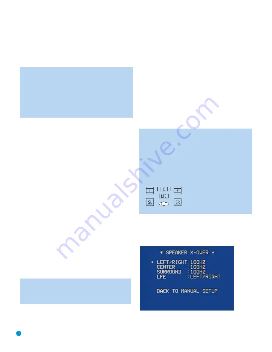
Speaker Crossover Menu
On the Manual Setup menu, move the cursor to the SPEAKER X-OVER
line and press the OK Button to display the Speaker Crossover menu.
See Figure 45.
Figure 45 – Speaker Crossover Menu Screen
Содержание Harman/kardon AVR 154
Страница 1: ...AVR 154 AUDIO VIDEO RECEIVER OWNER S MANUAL...
Страница 4: ...4 STAPLE INVOICE HERE...
Страница 59: ...59 NOTES...


