42
MULTIROOM OPERATION
Multiroom Operation
Multiroom Operation
The DPR is fully equipped to operate as the con-
trol center for a complete multiroom system that
is capable of sending one source to a second
zone in the house while separate source is lis-
tened to in the main room. In addition to provid-
ing for control over the selection of the remote
source and its volume, the DPR offers a compre-
hensive range of options for powering the speak-
ers in the second zone.
• Using the line-level
Multiroom Audio
Outputs
"
, the selected source may be fed to
optional, external power amplifiers that may be
matched to the specifics of the installation.
• When the main room system is configured for
5.1 operation, the Surround Back Left/Right
amplifier channels may be used to power the
remote zone so that no additional amplifiers are
required.
• Using built-in A-BUS Ready technology, option-
al A-BUS modules may be connected to the DPR
via a single Category Five wire, so that remote
zone speakers may be powered directly from the
module or keypad without the need for additional
power, IR sensor or volume control wires to be
run to the second zone.
In addition, the DPR includes a remote IR sensor
input so that remote control commands from the
Zone II remote included with the unit may be
transmitted to the unit, while standard IR
input/output jacks allow the remote zone’s com-
mands to be sent to compatible IR-controlled
source devices.
Installation
Although simple remote room systems may be
installed by the average do-it-yourself hobbyist,
the complexity of your multizone/multiroom sys-
tem involves running wires inside of walls where
the services of a specially trained installer may be
required. Regardless of who does the work,
please remember that local building codes may
govern in-wall electrical work, including proper
specification of any wiring used and the way in
which it is connected. You are responsible for
making certain that all Multiroom installation
work is done properly and in compliance with all
applicable codes and regulations.
For standard installations, follow the instructions
shown on page 16 and 18 for the connection of
speaker wire and IR remote wiring to the DPR.
For installations where the Surround Back
Left/Right amplifier channels are used to power
the remote zone, make certain that the system is
configured for that type of operation, as shown
on page 40.
For installations where A-BUS modules are used,
follow the instructions provided with the A-BUS
remote modules or keypads.
Additional information will also be made avail-
able through the Harman Kardon Web Site at
www.harmankardon.com.
RS-232 Control
The DPR is rare among A/V receivers in that it
provides the capability for full remote control
from compatible computers or specialized remote
control systems. RS-232 programming requires
specialized programming knowledge and for that
reason we recommend that it only be done by
qualified installers.
NOTE: The RS-232 port on this product is
for use by authorized service personnel
ONLY.
Multiroom Setup
Once the audio and IR link connections have
been made, the DPR needs to be configured for
multiroom operation using the steps below. Press
the
OSD
button
L
to bring the
M A S T E R
M E N U
(Figure 1) to the screen. Press the
⁄
button
E
twice, until the on-screen
›
cursor is
next to the
MULTI-ROOM
line. Press the
Set
button
F
to enter the
MULTI-ROOM
menu
(Figure 13).
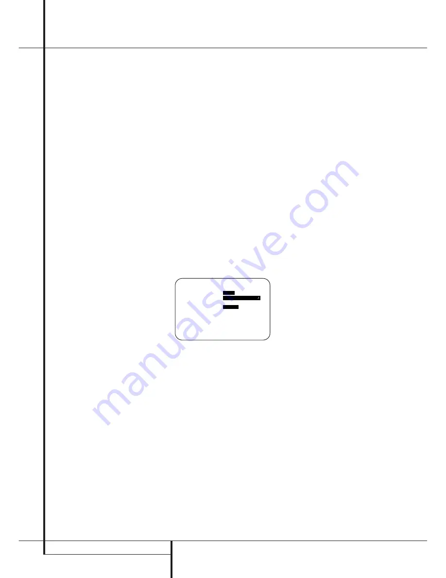
Figure 13
When the
MULTI-ROOM
menu appears, the
on-screen
›
cursor will be at the
MULTI-
ROOM
line. Since this line is used to turn the
system on and off, do not make an adjustment
here unless you wish to turn the system on at this
time. To turn the system on, press the
›
button
E
so that
O N
is highlighted. If you do not wish
to turn the system on at this time or to proceed
to the next step, press the
¤
Button
E
once so
that the
›
on-screen cursor is next to the
MULTI I N
line.
At the
MULTI I N
line, press the
‹
/
›
buttons
E
until the desired Audio/Video input to the
multi-room system appears in the highlighted
video.
In addition to the standard inputs, a choice is
available labeled
MAIN DOWNMIX
. In all
other cases, the feed to the multiroom system
may be different from the input selected for the
main room, but the input must be analog. When
MAIN DOWNMIX
is selected as the multi-
room system input you may listen to an “Lt/Rt”
stereo version of any digital source playing in the
main room, such as Dolby Digital or DTS. You may
also use this mode to listen to a source connect-
ed to the
8-Channel Direct Inputs
'
in the
remote zone, as long as the Dolby Pro Logic IIx
mode is activated. Note, however, that when
MAIN DOWNMIX
is selected as the input for
the multiroom system, the source sent to the
remote room will change any time the main room
input is changed.
When the selection has been made, press the
¤
button
E
once so that the
›
on-screen cursor
is next to the
MULTI VOL
line.
At the
MULTI VOL
line, press the
‹
/
›
but-
tons
E
or hold them pressed until the desired
volume level for the multi-room system is
entered. DO NOT use the regular volume control
knobs for this setting. When all settings for the
multiroom setup have been made, press the
¤
buttons
E
once so that the on-screen
›
cursor
is next to the
BACK T O MASTER MENU
line and press the
Set
button
F
. If you have no
other adjustments to make, press the
OSD
button
L
to exit the menu system.
Multiroom Operation
When operating the DPR from a remote room
location where an IR sensor link has been con-
nected to the DPR’s rear panel
Multiroom IR
Input
, you may use either the Main remote
control or the Zone II remote. To turn on the
multiroom feed, press any of the
Input Selector
buttons on the Zone II remote
∫ç∂
or the
Main remote
456
. Press the
AVR
Selector
5
∫
to turn the unit on to the last
source, or any of the other Selector buttons to
turn on to a specific source.
As long as an IR feed to the DPR has been estab-
lished from the remote room, using any of the
buttons on either remote will control the remote
location volume
)
î
, change the tuner
frequency
K
è
, change the tuner preset
"
©
or mute the output
,
˚
.
If the
Remote IR Output
jack
on the DPR is
connected to an IR Input jack on compatible
Harman Kardon audio components such as CD,
DVD or cassette players, the transport functions
of those machines may also be controlled using
the
Transport Controls
P
Ƀ
©˙∆
on either remote control.
To turn the system off from the remote room,
press the
Power-Off
button
0
å
. Remember
that the DPR may be turned on or off from the
remote room regardless of the system’s operation
or status in the main room.
NOTE:
When the tuner is selected as the source
for the remote zone, any change to the frequency
or preset will also change the station being lis-
tened to in the main room, if the tuner is in use
there. Similarly, if someone in the main room
* M U L T I - R O O M S E T U P *
M U L T I - R O O M :
O F F
O N
M U L T I I N :
F M P R E S E T 0 1
M U L T I V O L : # 2 5 d B
S B A M P S :
M A I N
M U L T I
B A C K T O M A S T E R M E N U
→