ENGL
ISH
INSTALLATION
IMPORTANT NOTE
: All components, including the BDP 10, should
be turned off and unplugged from AC power before beginning
installation. Do not plug any components back in until after all
connections are completed.
Step One – Placement
Other system components, especially audio/video receivers and
amplifiers, generate massive amounts of heat that will damage the
sensitive laser components of the BDP 10. Although the BDP 10 is
equipped with a fan that will turn on occasionally to compensate for
heat conditions, it is strongly recommended that you place the BDP 10
on its own shelf. Do not stack components on top of each other.
Step Two – Connect the BDP 10 to an A/V Receiver
or Processor (Preferred)
)FTHERECEIVERIS($-)CAPABLECONNECTTHE($-)/UTPUTTOTHE
RECEIVERS($-)INPUT3EE&IGURE
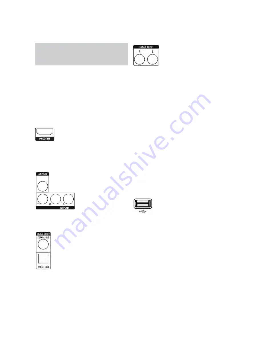
&IGUREn($-)/UTPUT
)FTHERECEIVERHASA$6)INPUTANDIS($#0COMPLIANTUSEAN($-)
to-DVI adapter, and make a separate audio connection.
)FTHERECEIVERDOESNOTHAVEAN($-)OR$6)INPUTSELECTONEVIDEO
connection, in order of preference: component video or composite
video. See Figure 2.
Figure 2 – Component and Composite Video Outputs
&ORNON($-)PRODUCTSASEPARATEAUDIOCONNECTIONISREQUIRED)F
available, connect either the Optical or Coaxial Digital Audio Output to
the receiver. See Figure 3.
Figure 3 – Coaxial and Optical Digital Audio Outputs
Connect the Analog Audio Outputs to a receiver that does not have
an available digital audio input. If digital audio connections have been
made to the receiver, make an analog connection for recording,
multizone systems or as a backup. See Figure 4.
Figure 4 – Analog Audio Outputs
Skip to Step Four.
Step Three – Connect the BDP 10 Directly to a
Television (Alternate)
If an A / V receiver or processor was used, you may skip this step, or
you may make a second connection from the BDP 10 directly to the
TV to bypass the home theater system for casual viewing. If you do
not have an audio system, connect the BDP 10 to the TV as explained
below.
)FTHETELEVISIONIS($-)CAPABLECONNECTTHE($-)/UTPUTTOTHE46S
($-)INPUT3EE&IGURE
)FTHE46HASONLYA$6)INPUTANDIS($#0COMPLIANTUSEAN($-)
to-DVI adapter, and make a separate audio connection.
)FTHETELEVISIONDOESNOTHAVEAN($-)OR$6)INPUTSELECTONEVIDEO
connection, in order of preference: component video or composite
video. See Figure 2.
&ORNON($-)46SASEPARATEAUDIOCONNECTIONISREQUIRED!LTHOUGH
some TVs may be equipped with an optical or coaxial digital audio
connection, most likely you will use a 2-channel analog connection.
Connect the Analog Audio Outputs shown in Figure 4 to the TV.
Step Four – Connect a USB Storage Device
Connect a compatible USB client device to the front-panel USB port.
The USB drive may be used as virtual memory for the BD-Live system,
or as a playback source. See Figure 5 and page 22.
Figure 5 – Front-Panel USB Port
Step Five – Connect the Remote IR Input and
Output (Optional)
Connect the BDP 10’s Remote IR Input to the compatible IR output
of another product, or to an IR receiver or controller, such as the
optional Harman Kardon HE 1000. When daisychaining devices to
allow for remote control up and down the chain, connect the Remote
IR Output to the next product’s IR input. See Figure 6. The BDP 10 is
compatible with “stripped carrier” IR signals.
for BDP10
17
harman/kardon
BDP 1 / BDP 10 Service Manual
Содержание BDP 1/120
Страница 32: ...Front Board Print layout Top side 32 harman kardon BDP 1 BDP 10 Service Manual...
Страница 33: ...Front Board Print layout Bottom side 33 harman kardon BDP 1 BDP 10 Service Manual...
Страница 34: ...IR Board Print layout Bottom side 34 harman kardon BDP 1 BDP 10 Service Manual...
Страница 35: ...Power Board Print layout Bottom side 35 harman kardon BDP 1 BDP 10 Service Manual...
Страница 36: ...Main Board Print layout Top side 7 20 36 harman kardon BDP 1 BDP 10 Service Manual...
Страница 37: ...Main Board Print layout Bottom side 37 harman kardon BDP 1 BDP 10 Service Manual...


