


IMPORTANT NOTE:
The AVR 155’s remote may
be programmed to control up to seven devices,
including the AVR. Before using the remote, it is
important to remember to press the
Input
Selector
button
45
that corresponds to
the unit you wish to operate. In addition, the
AVR’s remote is shipped from the factory to
operate the AVR and most Harman Kardon CD
or DVD players and cassette decks. The remote is
also capable of operating a wide variety of other
products using the control codes that are part of
the remote. Before using the remote with other
products, follow the instructions on pages 50-51
to program the proper codes for the products in
your system.
It is also important to remember that many of
the buttons on the remote take on different
functions, depending on the product selected
using the
Input Selector Button
4
. The
descriptions shown here primarily detail the
functions of the remote when it is used to operate
the AVR. (See page 46-47 for information about
alternate functions for the remote’s buttons.)
0
Power Off Button:
Press this button to
place the AVR or a selected device unit in the
Standby mode.
1
IR Transmitter Window:
Point this window
towards the AVR when pressing buttons on the
remote to make certain that infrared commands
are properly received.
2
Program Indicator:
This three-color
indicator is used to guide you through the
process of programming the remote. (See page
43 for information on programming the remote.)
3
Power On Button:
Press this button to
turn on the power to a device selected by pressing
one of the
Input Selectors
4
(except Tape).
4
Input Selectors:
Pressing one of these
buttons will perform three actions at the same
time. First, if the AVR is not turned on, this will
power up the unit. Next, it will select the source
shown on the button as the input to the AVR.
Finally, it will change the remote control so that
it controls the device selected.
After pressing one of these buttons you must
press the
AVR Selector
button
5
again to
operate the AVR’s functions with the remote.
5
AVR Selector:
Pressing this button will
switch the remote so that it will operate the
AVR’s functions. If the AVR is in the Standby
mode, it will also turn the AVR on.
6
AM/FM Tuner Select:
Press this button to
select the AVR’s tuner as the listening choice.
Pressing this button when the tuner is in use will
select between the AM and FM bands.
7
6-Channel Direct Input:
Press this
button to select the device connected to the
6-Channel Direct Inputs
9
.
8
Test Tone:
Press this button to begin the
sequence used to calibrate the AVR’s output
levels. (See page 23-24 for more information on
calibrating the AVR).
9
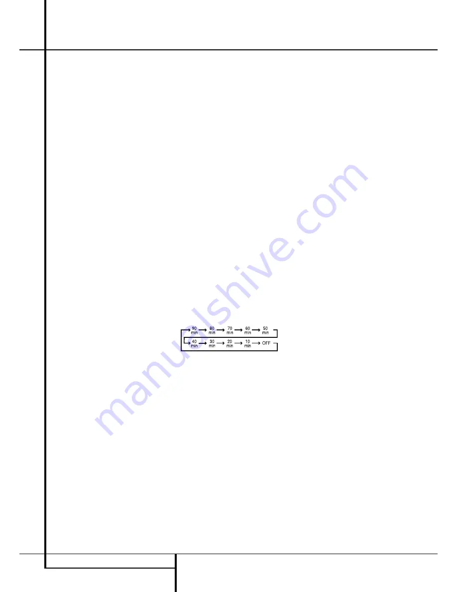
Sleep Button:
Press this button to place
the unit in the Sleep mode. After the time shown
in the display, the AVR will automatically go into
the Standby mode. Each press of the button
changes the time until turn-off in the following
order:
Hold the button pressed for two seconds to turn
off the Sleep mode setting.
Note that this button is also used to change
channels on your TV, VCR and Sat receiver when
the appropriate source is selected, using the
device
Input Selectors
4
.
A
Surround Mode Selector:
Press this but-
ton to select any of the HALL, THEATER surround
modes. Note that depending on the type of
input, some modes are not always available.
(See page 34-35 for more information about
surround modes.) Note that this button is also
used to tune channels on your TV, VCR and Sat
receiver when the appropriate source is selected
using the device
Input Selector
4
.
B
Night Mode:
Press this button to activate
the Night mode. This mode is available only with
Dolby Digital encoded sources, and it preserves
dialog (center channel) intelligibilty at low
volume levels (See page 36 for more
information).
C
Channel Select Button:
This button is
used to start the process of setting the AVR’s
output levels with an external source. Once this
button is pressed, use the
⁄
/
¤
buttons
D
to
select the channel being adjusted, then press the
OK
button
F
, followed by the
⁄
/
¤
buttons
D
again, to change the level setting.
(See page 23-24 for more information.)
D
⁄
/
¤
Buttons:
These multipurpose but-
tons are used to change or scroll through items
in the on-screen menus or on the front panel or
to make configuration settings such as digital
inputs or delay timing. When changing a setting,
first press the button for the function or setting
to be changed (e.g., press the
Digital Select
Button
G
to change a digital input) and then
press one of these buttons to scroll through the
list of options or to increase or decrease a
setting. The sections in this manual describing
the individual features and functions contain
specific information on using these buttons for
each application.
When the AVR remote is being programmed for
the codes of another device, these buttons are
also used in the “Auto Search” process (See
page 43 for more information on programming
the remote.)
10
MAIN REMOTE CONTROL FUNCTIONS
Main Remote Control Functions


