Harman Kardon AVR 155 Скачать руководство пользователя страница 25

SYSTEM CONFIGURATION 

25

ENGLISH

System Configuration

when the AVR is being used with a digital
source that contains a dedicated Low
Frequency Effects, or LFE soundtrack. This
allows you to use both your main and sub-
woofer speakers to take advantage of the spe-
cial bass created for certain movies. To select
that option press the 

/

Buttons

E

on

the remote so that 

LFE

appears in the on-

screen menu.

• If a subwoofer is connected and you wish to

use it for bass reproduction in conjunction with
the main front left/right speakers, regardless of
the type of program source or Surround mode
you are listening to, press the 

/

Buttons

E

on the remote so that 

L/R+LFE

appears in the on-screen menu. When this
option is selected, a full-range signal will be
sent to the front left/right “main” speakers. The
subwoofer will receive the front left and right
bass frequencies under the crossover frequency
selected in another setting on this menu, as
described below, and also the LFE soundtrack.

9. When all initial speaker “size” settings have
been made, you now have the option to take
advantage of the AVR’s Triple Crossover system,
which allows individual crossover settings to be
made for each speaker group. In systems where
full-range or tower speakers are used for the
front soundstage or where different brands or
models are in use at the various speaker posi-
tions, this feature allows you to custom tailor the
bass management and redirection circuits with a
precision not previously possible. 

If you have already run EzSet/EQ the settings
 calculated during that procedure will already
appear. No further adjustment is required unless
you wish to conform a specific item to your
 personal taste or a nonstandard system
 configuration.

The low-frequency crossover point is set by the
design of your speakers. It is defined as the fre-
quency which is the lowest possible frequency
the speaker is capable of reproducing. Before
making any changes to the settings for the
crossover point we suggest that you find the
crossover point for the speakers in each of the
three groupings, front left/right, center front and
surrounds by looking at the specifications page of
the speaker’s owner’s manual, by getting that
information from the manufacturer’s Web site, or
by contacting your dealer or the manufacturer’s
customer service department. You will need this
figure to accurately configure the next group of
settings.

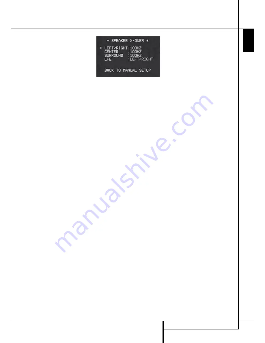
The factory default setting for all speaker posi-
tions is 100Hz. If that setting is acceptable for all
channels, then no adjustments are needed and
you may skip this section. However, should you
wish to change one of the settings, please pro-
ceed to the 

SPEAKER X-OVER

submenu, as

shown in Figure 8.

Figure 8

To change the setting for any of the three
 speaker groups Left/Right, Center or Surround,
press the 

/

¤

Buttons

D

until the cursor is

next to the line where you wish to make a
change and then press the 

/

Buttons

E

until the desired setting appears. The available
choices at which point low-frequency information
will be sent to the subwoofer (or to the Front
Left/Right speakers in case subwoofer is set to
OFF), rather than to the speaker channel, are
40Hz, 60Hz, 80Hz, 100Hz, 120Hz, 150Hz and
200Hz. Pick the choice that is identical to the
information for the speakers, or if an exact match
is not possible, pick the closest choice that is
ABOVE the speaker’s lowfrequency limit to avoid
the creation of a low-frequency “hole” where
your system will have no bass information.

In cases where 

LARGE

has been selected as the

front channel speaker option and 

L/R+LFE

has been selected as the subwoofer option, the
front channel sound information below the cross -
over point selected for the L/R front speakers
(when fronts are set to "Small") will be sent to
BOTH the front channel speakers and the sub-
woofer.

The crossover settings for the Left/Right, Center
and Surround speakers are used to determine
where bass information is sent when it is derived
from the main channels of a source. The setting
for the menu line shown as 

LFE

is used to

impose a low-pass filter point for the information
in the Low Frequency Effects (LFE) channel that is
a part of Dolby Digital- and DTS-encoded source
material. While the LFE channel, which is the
“.1” you see in surround sound designations, is
restricted to low frequency sounds, some mixes
may include information that is higher in frequen-
cy than your subwoofer is capable of reproduc-
ing. To prevent unwanted sounds from being sent
to subwoofers that  cannot handle them and
which do not have a built-in low-pass filter, the

LFE

option line enables you to select a setting

for the low-pass filter that is part of the sub-
woofer feed from the LFE channel. 

The settings available are the same as those tied
to any one of the four available speaker positions
on this submenu. We recommend that you use
the frequency that is just slightly higher than the
upper capability limit of your subwoofer, as
shown in the sub’s Owner’s Manual. When the
cursor is on the 

LFE

line, press the 

/

Navigation Buttons

E

to choose the

appropriate setting.

Note that the crossover point for the surround
speakers and the surround back speakers will be
identical. That´s why no crossover point for the
surround back speakers is selectable or shown in
the menu. 

Important Note

: All settings for the crossover

points will be "Global", i.e. they will be identical
for all inputs no matter if the BASSMANAGER
(see above) was configured for "Global" or
"Independent".

10. When all speaker selections have been made,
press the 

¤

Button

D

until the cursor is next

to the 

BACK TO MANUAL SETUP

line and

press the 

OK Button

F

to return to the

Manual setup submenu.

11. The Speaker Configuration may also be
changed at any time without using the full-OSD
on-screen menu system by pressing the 

Speaker

Selector

6

on the front panel or 

on the

remote control. Once the button is pressed,

FRONT SPEAKER

will appear in both the

lower third of the video display and the 

Main

Information Display

Ò

Within five seconds, either press the 

/

buttons

7

on the front panel or the 

/

¤

buttons 

D

on the remote to select a different speaker
 position, or press the 

OK 

Button 

@

F

to

begin the adjustment process for the front left
and right speakers.

When the 

OK 

button 

@

F

has been pressed

and the system is ready for a change to the front
speaker setting, the on-screen display and 

Main

Information Display

Ò

will read 

FRONT

LARGE

or 

FRONT SMALL

depending on the

current setting. Press the 

/

buttons 

7

on the

front panel or the 

/

¤

buttons 

D

on the

remote until the desired setting is shown, using
the instructions for “large” or “small” shown
earlier, then press the 

OK 

button 

@

F

.

If another speaker position needs to be changed,
press the 

/

buttons 

7

on the front panel or

the 

/

¤

buttons 

D

on the remote to select a

different speaker position, press the 

OK 

button

@

F

and then the 

/

buttons 

7

on the

front panel or the 

/

¤

buttons 

D

on the

remote until the correct speaker setting is shown
and press the 

OK 

button 

@

F

again to

 confirm the selection.

To assist in making these settings, the icons in
the 

Speaker/Channel Input Indicators

$

will change as the speaker type is selected at
each position. When only the inner icon box is lit,
the speaker is set for “small.” When the inner box
and the two outer boxes with circles inside them
are lit, the speaker is set for “large." When no
indicator appears at a speaker location, that
 position is set for “none” or “no” speaker.

Содержание AVR 155

Страница 1: ...ENGLISH AVR 155 Audio VideoReceiver OWNER S MANUAL ...

Страница 2: ...42 RDS Display Options 42 Program Search PTY 43 Programming the Remote 43 Programming the Remote with Codes Table of Contents Typographical Conventions In order to help you use this manual with the remote control front panel controls and rear panel connections certain conventions have been used EXAMPLE bold type indicates a specific remote control or front panel button or rear panel connection jac...

Страница 3: ...igital audio sources For compatibility with the latest HDTV video sources and progressive scan DVD players the AVR also features wide bandwidth low crosstalk component video switching Coax and optical digital outputs are available for direct connection to digital recorders A video recording output and a color coded six channel input make the AVR 155 virtually future proof with everything needed to...

Страница 4: ...ng the unit on a shelf be certain that the shelf and any mounting hardware can support the weight of the product n Make certain that proper space is provided both above and below the unit for ventilation If this product will be installed in a cabinet or other enclosed area make certain that there is sufficient air movement within the cabinet Under some circumstances a fan may be required n Do not ...

Страница 5: ...t is in operation the indicator will turn white 4 Headphone Jack This jack may be used to listen to the AVR s output through a pair of head phones Be certain that the headphones have a standard 6 3 mm stereo phone plug Note that the speakers will automatically be turned off when the headphones are connected When configuring your system using EzSet EQ the calibration microphone should be plugged in...

Страница 6: ...guration The left center right right surround and left surround speaker indicators are composed of three boxes while the subwoofer is a single box The center box lights when a Small speaker is selected and the two outer boxes light when Large speakers are selected When none of the boxes are lit for the center surround or subwoofer channels no speaker has been selected for that position See page 23...

Страница 7: ...urround Right Gray Subwoofer LFE Purple Digital Audio Orange Composite Video Yellow Component Video Y Green Component Video Pr Red Component Video Pb Blue 0 AM Antenna Connect theAM loop antenna supplied with the receiver to these terminals If an externalAM antenna is used make connections to the AM and GND terminals in accordance with the instructions supplied with the antenna 1 FM Antenna Connec...

Страница 8: ...ent video outputs to these jacks K Monitor Component Video Outputs Connect these outputs to the component video inputs of a video projector or monitor When a source connected to one of the two Component Video Inputs JL is selected the signal will be sent to these jacks L Video 1 Component Video Inputs Connect the Y Pr Pb component video outputs of a DVD player to these jacks Note All component inp...

Страница 9: ... Select Button DTS Digital Mode Selector Logic 7 Mode Select Button Transport Controls Tone Mode Skip Up Down Buttons Stereo Mode Select Button DTS Neo 6 Mode Select Macro Buttons RDS Selector Button Preset Up Down Clear Button Memory Button Delay Prev Ch Button Speaker Select Mute Volume Up Down TV Video Selector Dim Button NOTE The function names shown here are each button s feature when used wi...

Страница 10: ... 7 6 Channel Direct Input Press this button to select the device connected to the 6 Channel Direct Inputs 9 8 Test Tone Press this button to begin the sequence used to calibrate the AVR s output levels See page 23 24 for more information on calibrating the AVR 9 Sleep Button Press this button to place the unit in the Sleep mode After the time shown in the display the AVR will automatically go into...

Страница 11: ...urround material played and the speaker setting When a DTS source is not in use this button has no function See page 36 for the available DTS options O Logic 7 Selector Press this button to select one of the available Logic 7 surround modes See page 36 for the available Logic 7 options P Transport Control Buttons These buttons do not have any functions for the AVR but they may be programmed for th...

Страница 12: ...or more information on programming the remote Volume Up Down Press these buttons to raise or lower the system volume TV Video Button This button does not have a direct function on the AVR but when used with a compatibly programmed VCR DVD or satellite receiver that has a TV Video function pressing this button will switch between the output of the player or receiver and the external video input to ...

Страница 13: ... you use personal preferences and other factors Your dealer or installer is a valuable resource to consult in selecting the proper cable Regardless of the brand of cable selected we re commend that you use a cable constructed of fine multistrand copper with an area greater than 2 mm2 Cable with an area of 1 5 mm2 may be used for short runs of less than 4 m We do not recom mend that you use cables ...

Страница 14: ...s Any normal video device Not SVHS or High 8 for only playback needs 3 RCA jacks VCRs for record and playback even 6 RCA jacks Any S Video device SVHS High 8 needs 2 RCA Audio and 1 S Video jack Video if it s a play back unit or 4 RCA Audio In Out and 2 S Video Video In Out jacks if it s a recording VCR Many european video devices are equipped with RCA Cinch or S Video jacks only partially not for...

Страница 15: ...s with selectable 16 9 format and turning the RGB video decoder of the TV on or off depending on the DVD player s setting With any adapter cable these control signals will be lost and the appropriate setting of the TV must be made manually Note for RGB signal with SCART If you use a unit providing RGB signals on a SCART output as e g most DVD players do and you want to use that RGB signal this SCA...

Страница 16: ...eakers in use you may find that imaging is improved by moving the front left and front right speakers slightly for ward of the center channel speaker If possible adjust all front loudspeakers so that they are aimed at ear height when you are seated in the listening position Using these guidelines you ll find that it takes some experimentation to find the correct location for the front speakers in ...

Страница 17: ...ll OSD When making configuration adjustments it is recommended that the Full OSD mode be used This will place a complete status report or option listing on the screen making it easier to view the available options and make the settings on the screen The Semi OSD mode uses one line displays only Note that when the full OSD system is in use the menu selections are not shown in the Infor mation Displ...

Страница 18: ...ollowed by the lower case letters and then numbers and symbols When you press the Navigation Button D a series of symbols and numbers will appear followed by a reverse list of the alphabet in lower case letters Press the button either way until the first letter of the desired name appears If you wish to enter a blank space as the first character press the Navigation Button When the desired charact...

Страница 19: ... complete explanation of these modes is found on Page 30 31 Note that when the Dolby Digital mode is selected there are additional settings available for the Night mode that are associated with the surround mode only not with the input That s why these settings must be made only once not with each input in use They are described later in the next main chapter see below Figure 4 When the fi cursor ...

Страница 20: ... by pressing the Stereo Mode Selector until SURROUND OFF appears in the Main Information Display Ò the AVR will pass the analog source material directly through to the front left and right speakers bypassing the digital processing circuitry In this mode the front left and right speakers will automatically be configured as LARGE it is not possible to configure these speakers as SMALL When the AVR i...

Страница 21: ... E for the arrow to point to NO and then press the OK Button F to return to the MASTER MENU Note that if you attempt to move to the next menu without plugging in the microphone a reminder message will flash at the bottom of the screen Figure 5a Step 6 After entering YES to start the EzSet EQ system you will next see a brief warn ing message and the screen will then change to the main EzSet EQ menu...

Страница 22: ...ay use the results of the automated testing as a baseline and then make manual adjustments to the speaker size settings on a source independent basis following the instructions shown on page 23 27 When this test is complete an output level adjustment number will be shown to the right of the SPEAKER SIZE line on the menu screen Speaker Crossover The measurements and calculations for this test take ...

Страница 23: ... to NO If you have not run EzSet the setting is NO and cannot be changed The next four lines of the Manual Setup menu are used to access the four submenus used during the setup process Each submenu s settings are dependent upon the previous submenu and therefore we recommend you visit the menus in the order shown Speaker Setup This menu tells the AVR which type of speakers are in use This is impor...

Страница 24: ...two front satellites connected to the Sub s speaker outputs is used the Sub s inputs must be connected to the Front speaker outputs D and LARGE must be selected for the front speakers and NONE for the subwoofer see below 3 When you have completed your selection for the front channel press the Button D on the remote to move the cursor to CENTER 4 Press the Buttons E on the remote to select the opti...

Страница 25: ...option the front channel sound information below the cross over point selected for the L R front speakers when fronts are set to Small will be sent to BOTH the front channel speakers and the sub woofer The crossover settings for the Left Right Center and Surround speakers are used to determine where bass information is sent when it is derived from the main channels of a source The setting for the ...

Страница 26: ...settings at first select the DELAY ADJUST MENU Figure 9 If the sys tem is not already at that point press the OSD button L to bring up the master menu Press the Button D three times or until the on screen fi cursor is pointing at the MANUAL SETUP line Press the OK Button F and call up the DELAY ADJUST submenu Figure 9 Next move the fi cursor to the UNIT line and select the unit for distances you p...

Страница 27: ...stem using EzSet EQ the output level adjustments shown will reflect the results of the measurements made by EzSet EQ No further changes are needed unless you wish to change a specific item to reflect your personal taste or a non standard system configuration IMPORTANT NOTE The output level can be adjusted for each digital and analog surround mode individually This allows you to compensate for leve...

Страница 28: ...n the remote 7 Continue to adjust the individual channels until the volume level sounds the same from each speaker Note that adjustments should be made with the Buttons E on the remote only NOT the main volume controls If you are using a sound pressure level SPL meter for precise level adjustment with the test tone open the main Volume Control to 15dB and set the individual output level for each c...

Страница 29: ...or 8 button again to turn the test tone off and complete the process IMPORTANT NOTE The Output level adjust ment made will be effective for all inputs but only for the actual surround mode selected To be effective for any other mode select that mode with any input and repeat the level adjustment described above This will also allow you to compensate level differences between speakers that may be d...

Страница 30: ...n with normal stereo mode creating separate rear left and rear right signals in any case The Pro Logic II mode creates compelling five channel surround sound from conventional stereo recordings Game mode ensures that special effects are routed to the surround channels while delivering their full impact using the subwoofer thus fully immersing the game player in the universe of the video game Logic...

Страница 31: ...system using only front left and right speakers In the Wide Reference Mode the apparent width of the sound across the front image is defined by the distance between the two speakers The Wide Mode provides a wider more spacious front image when the two speakers areclose together THEATER The THEATER mode creates a sound field that resembles the acoustic feeling of a standard live performance theater...

Страница 32: ... your home entertainment system on a temporary basis As the input source is changed the new input name will appear momentarily as an on screen display in the lower third of the video display The input name will also appear in the Main Information Display Ò When a pure audio input CD Tuner Tape 6 Channel Input is selected the last video input used remains routed to the Video Outputs P and Video Mon...

Страница 33: ...the remote control press the button for the major surround mode group that includes the mode you wish to choose from Dolby M DTS Surround N DTS Neo 6 Logic 7 O Stereo or DSP Surround A The first press of the button will show the current mode from that group if it is already in use or the first available mode if you are currently using another mode To cycle through the available modes in that group...

Страница 34: ...ut need not be re selected each time the appropriate input choice e g DVD is made Digital Bitstream Indicators When a digital source is playing the AVR senses the type of bitstream data that is present Using this information the correct surround mode will automatically be selected For example DTS bit streams will cause the unit to switch to DTS decoding and Dolby Digital bitstreams will enable Dol...

Страница 35: ...dout of the sampling frequency of the digital signal Connections may be made to either the rear panel Optical or Coaxial Inputs RN or the front panel Digital Inputs Ó To listen to a PCM digital source first select the input for the desired source e g CD Next press the Digital Select Button ÛG and then use the Buttons D on the remote or the Selector Buttons 7 on the front panel until the desired ch...

Страница 36: ...e menus to set this option IMPORTANT NOTES ON DIGITAL PLAYBACK When the digital playback source is stopped or in a pause fast forward or chapter search mode the digital audio data will momentarily stop and the channel position letters inside the Speaker Channel Indicators will flash This is nor mal and does not indicate a problem with either the AVR or the source machine The AVR will return to dig...

Страница 37: ...ns 7 or the buttons D until WOOFER LEVEL appears in the Main Information Display Ò or on screen display only available if the subwoofer is turned on Press the OK button F when the name of the desired channel appears in the Main Information Display Ò and on screen dis play and follow the instructions shown above to adjust the level Repeat the procedure as needed until all chan nels requiring adjust...

Страница 38: ...es to the front panel brightness level are temporary the displays will return to full brightness after the AVR is turned off and then on again To return the displays to full brightness without turning the unit off press the Dim Button as needed until the displays are on In addition to lowering the brightness of the dis plays or turning them off completely you may wish to have them appear whenever ...

Страница 39: ...is shown on the DEFAULT VOL SET line Note that this setting may NOT be made with the regular volume controls NOTE Since the setting for the turn on volume cannot be heard while the setting is being made you may wish to determine the setting before making the adjustment To do this listen to any source and adjust the volume to the desired level using the regular volume controls When the desired volu...

Страница 40: ...ish to hear when Dolby Digital or DTS is present The AVR allows you to set the unit so that it will either respond to the default or switch to your desired mode If you wish to leave the default so that the mode choice encoded in the disc is always used no further action is needed Simply leave the setting at the factory default of ON To set the unit so that it responds to the last sur round mode us...

Страница 41: ...espond to the station s frequency Note that for entering numbers higher than 100 you need to enter only the 1 rather than 10 the first 0 will be added automatically The desired station will automatically be tuned after the latest number is entered If you press an incorrect button while entering a direct frequency press the Clear button to start over NOTE When the FM reception of a stereo station i...

Страница 42: ... NO TYPE NO TEXT or NO TIME message after the individual time out In any FM mode the RDS function requires a strong enough signal for proper operation Program Search PTY An important feature of RDS is its capability of encoding broadcasts with Program Type PTY codes that indicate the type of material being broadcast The following list shows the abbreviations used to indicate each PTY along with an...

Страница 43: ...the separate setup code guide or if not all functions operate properly try programming the remote with the Auto Search Method described below Note on Using the AVR remote with a Harman Kardon CD Recorder As shipped from the factory the remote is programmed for controlling Harman Kardon CD players It can also control most functions of the Harman Kardon CD Recorders see function list on page 46 47 t...

Страница 44: ...n A 4 The red LED under the Selector will go out and the Program Indicator 2 will turn green and flash three times before it goes out 5 When the Program Indicator 2 goes out the Macro has been erased Programmed Device Functions Once the AVR s remote has been programmed for the codes of other devices press the appropriate Input Selector 4 to change the remote from control over the AVR to the additi...

Страница 45: ...in the example above However press the same Input Selector in Steps 1 and 3 Transport Control Punch Through The AVR s remote may be programmed to operate so that the Transport Control Functions P Play Stop Fast Forward Rewind Pause and Record for a VCR DVD or CD will operate in conjunction with one of the other devices con trolled by the remote For example while using and controlling the TV you ma...

Страница 46: ...enu or Setup Intro Scan 23 Move Adjust Up Up 24 fi Move Adjust Left Left 25 OK OK Enter 26 fl Move Adjust Right Right 27 Move Adjust Down Down 28 Digital Exit Digital Input Select Open Close 29 Delay Prev Ch Delay Adjust Return or Status Open Close 30 1 1 1 1 1 31 2 2 2 2 2 32 3 3 3 3 3 33 4 4 4 4 4 34 5 5 5 5 5 35 6 6 6 6 6 36 7 7 7 7 7 37 8 8 8 8 8 38 Tun M Tuner Mode Chapter or Zoom Repeat 39 9 9...

Страница 47: ...Volume Up Volume Up 17 Surround CH Channel Channel Channel Channel Channel Channel 18 OSD OSD Live TV OSD OSD OSD OSD 19 Blank 20 Volume Down Volume Down Volume Down Volume Down Volume Down 21 Channel Guide Guide Info Guide Info Guide Guide 22 Speaker Menu Menu Menu Menu Menu Menu Menu 23 Up Up Up Up Up Up 24 fi Left Left Left Left Left Left 25 OK Enter Select Enter Enter Enter Set Enter 26 fl Right...

Страница 48: ...n service depot SYMPTOM CAUSE SOLUTION Unit does not function when Main No AC Power Make certain AC power cord is plugged Power Switch 2 is pushed into a live outlet Check to see if outlet is switch controlled Display lights but no sound Intermittent input connections Make certain that all input and speaker or picture connections are secure Mute is on Press Mute button Volume control is down Turn ...

Страница 49: ...ut Level Impedance 1Vp p 75 ohms Video Frequency Response Composite and S Video 10Hz 8MHz 3dB Video Frequency Response Component 10Hz 100MHz 3dB HDMI Switching General Power Requirement AC 220 240V 50Hz Power Consumption 65W idle 540W maximum 5 channels driven Dimensions Max Width 440mm Height 165mm Depth 382mm Weight 10 7 kg Depth measurement includes knobs buttons and terminal connections Height...

Страница 50: ...e Tuner 6 Channel DMP Bass Manager Global Left Right Speaker Size Small Small Small Small Small Small Small Small Small Small Large Center Speaker Size Small Small Small Small Small Small Small Small Small Small Large Surround Speaker Size Small Small Small Small Small Small Small Small Small Small Large Subwoofer Sub Sub Sub Sub Sub Sub Sub Sub Sub Sub Sub Left Right Speaker Crossover 100Hz 100Hz...

Страница 51: ...6 Channel Inputs are direct inputs meaning their signals are passed directly to the volume control without any bass management processing Thus the speaker sizes are always full range and it isn t possible to adjust speaker size or crossover Note Channel levels vary by surround mode rather than source input Table A6 Remote Control Codes Source Input Product Type circle one or fill in Remote Control...

Страница 52: ...250 Crossways Park Drive Woodbury New York 11797 www harmankardon com Harman Consumer Group Inc 2 route de Tours 72500 Château du Loir France 2008 Harman Kardon Incorporated Part No OM P N CQX1A1317Y ...

Отзывы: