


22
SYSTEM CONFIGURATION
System Configuration
•
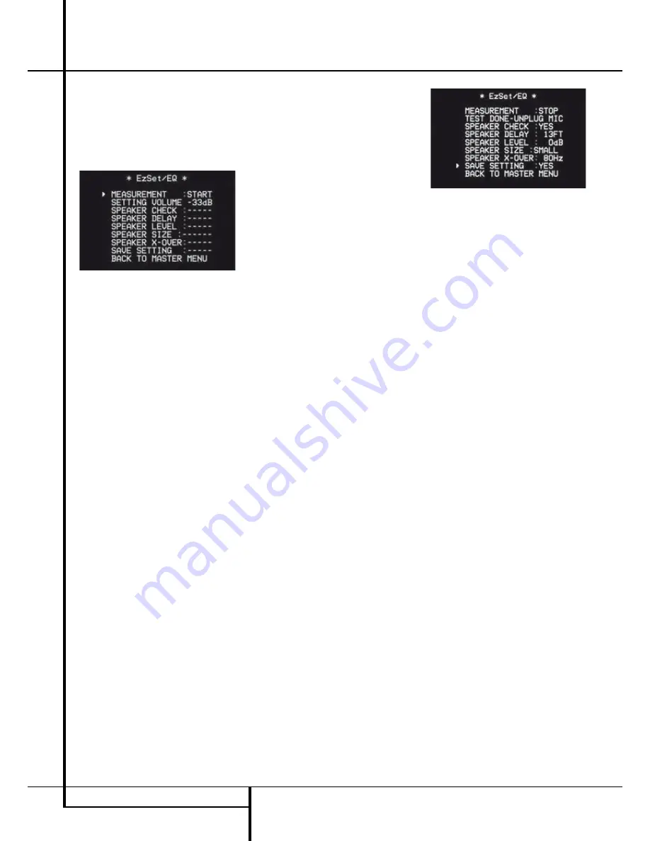
System Level:
A
SETTING VOLUME
message will appear to indicate that the
system is setting the overall volume level to the
proper level as a prelude to testing the
individual channels. During this test, you will
see a message in the last line of the menu
screen change as the volume level is adjusted.
Figure 5e
•
Speaker Check:
The system will circulate a
test signal to determine which channels have a
speaker connected. During this test, you will
see the name of each channel position dis-
played while a signal is sent to that speaker.
NOTE:
While this test detects whether a speak-
er is connected to a particular output, it cannot
determine whether the speaker is in the correct
position. (For example, it can tell whether a
speaker is connected to the Surround Right
output, but it cannot tell whether the speaker
is on the right or left side of your listening
room.) For that reason, we strongly recommend
that you try to listen as the tone circulates,
matching the name shown for each channel to
the location of the speaker. If a tone is heard
from a speaker position that does not match
the on-screen message, stop EzSet/EQ, exit the
menus, turn your receiver off and check for
proper speaker connections on the rear panel
before resuming the setup. When this test is
complete,
YES
will be shown to the right of
SPEAKER CHECK
on the menu screen.
•
Speaker Delay:
This test will circulate the
tones again as the name of each channel is
shown to measure the distance from the micro-
phone to each speaker. The results of these
tests will be used to set the delay time settings
for each active speaker position. When this test
is complete, a speaker-to-microphone (listening
position) distance will be shown to the right of
SPEAKER DELAY
line on the menu
screen.
•
Speaker Level:
This test circulates a test sig-
nal and measures the output from each active
speaker position. The results of the measure-
ments are used to adjust the individual channel
outputs as needed, so that they are identical.
This is an essential element of ensuring that
surround sound fields are properly reproduced.
If desired, you may use the results of the auto-
mated testing as a baseline and then make
manual adjustments to trim the output levels
to your personal taste, following the instruc-
tions shown on page 23-27. When this test is
complete, an output level adjustment number
will be shown to the right of
SPEAKER
LEVEL
line on the menu screen.
•
Speaker Size:
The measurements and calcula-
tions for this test take place at the same time
as the test signals are circulated to calculate
the output levels, and they are used to deter-
mine whether the speakers in your system are
“large” or “small” for the purposes of bass
management. (If desired, you may use the
results of the automated testing as a baseline
and then make manual adjustments to the
speaker size settings on a source-independent
basis, following the instructions shown on
page 23-27.) When this test is complete, an
output level adjustment number will be shown
to the right of the
SPEAKER SIZE
line on
the menu screen.
•
Speaker Crossover:
The measurements and
calculations for this test take place at the same
time as the test signal is circulated to calculate
the levels, and they are used to determine the
crossover setting for each speaker in your sys-
tem to create a seamless transition between
the frequencies sent to your main speakers and
subwoofer (if available). If desired, you may use
the results of the automated testing as a base-
line and then make manual adjustments to the
crossover settings on a source-independent
basis, following the instructions shown on
page 23-27. When this test is complete, a
cross over frequency will be shown to the right
of the
SPEAKER X-OVER
line on the
menu screen.
• Room Equalization: Each room has unique
characteristics that may affect the frequency
response at the listening position. For example,
doorways and alcoves can increase bass
response nearby. Varying surfaces such as hard
floors or windows, or soft carpets or draperies,
may also affect the way the room responds to
sound. Until now, expensive testing devices
and long hours of taking measurements and
adjusting room furnishings were required in
order to smooth out the frequency response to
avoid artifacts. EzSet/EQ simplifies equaliza-
tion, delivering world-class performance with-
out the extra expense. While the test tone cir-
culates, EzSet/EQ is able to obtain a sonic
“view” of the room and its characteristics, and
adjust the receiver’s output accordingly to cus-
tomize performance to the listening room.
Step 9:
When all measurements are successfully
completed, the test signals will stop and a
TEST DONE UNPLUG MIC
message will
appear in the second line of the on-screen menu
listings.
Figure 5f
Unplug the microphone and store it in a safe
place so that it is available to recalibrate your
system if needed due to a change in speakers,
preferred listening position, or a major change in
the room’s furnishings (such as the addition of
thick carpeting or plush furniture) that might
require different settings. To enter the settings to
the receiver’s memory and return to the Master
Menu, press the
⁄
/
¤
Navigation Buttons
D
so that the on-screen cursor is pointing to
RETURN TO MASTER MENU
and press the
OK Button
F
.
Note:
If you wish to check the test results before
exiting the EzSet/EQ menu, press the
⁄
/
¤
Navigation Buttons
D
so that the on-
screen cursor is at the second line of the menu
listings, and then press the
‹
/
›
Navigation
Buttons
E
to scroll through the list of
speaker positions. The data on each line will also
be entered into the listings on the individual
SPEAKER SETUP
,
DELAY ADJUST
and
CHANNEL ADJUST
menus once you exit
EZSET/EQ
.


