background image

AXIS LUBRICATION

- NOTE -

Grease should be added when the linear guides are still warm from operation.

X AND Z AXIS LUBRICATION ON TALENT

®

6/45 AND 8/52 LATHES

1. Wait for the cycle to end and that the spindles

and slides are stationary.

- NOTE -

Refer

to

the

Operator’s

Manual

(M-447) for information on using Rapid
Reference to move axes to the refer-
ence position.

2. Move the Z axis to the reference position.

3. Power down and lock out the machine. Refer to

the appropriate power-down procedure in
Chapter 1.

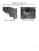
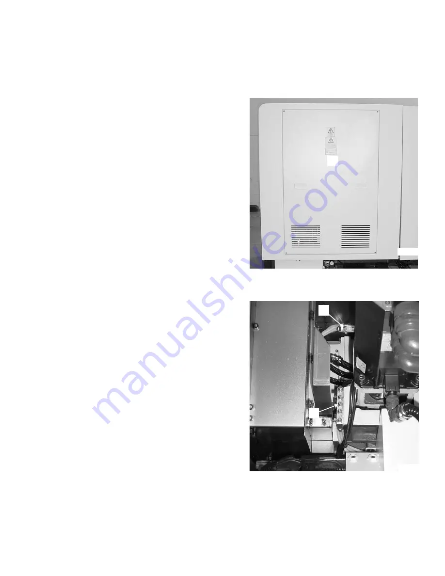
4. Remove cover “A”, Figure 2.1, to gain access

to the fittings on grease manifolds “B” and “C”,
Figure 2.2.

5. Clean the grease fittings.

- NOTE -

Only use a manually operated grease
gun.

Manifold “B” supplies grease to the X
axis. Manifold “C” supplies grease to
the Z axis.

6. Attach the grease gun nozzle to each grease

fitting; slowly and evenly pump in the specified
amount of grease.

7. Wipe the fittings clean of excess grease.

8. Install cover “A”, Figure 2.1.

9. Power

up

the

machine.

Refer

to

the

appropriate power-up procedure in Chapter 1.

10. If necessary, clear the lubrication alarm as

outlined in "Lubrication Alarm", page 2-2.

11. Jog the axes at 50% of the maximum rapid

traverse for a full 30 minutes before resuming
automatic machine operation.

M-448B

2-3

Figure 2.1 - Rear Access Cover

TP5196

A

Figure 2.2 - Grease Manifolds

TP5038

B

C

Содержание Talent 10/78

Страница 1: ...LENT 6 45 TALENT 8 52 TALENT 8 66 TALENT 10 78 CNC LATHES Equipped with a Fanuc 0i T Fanuc 0i Mate T or Siemens 810D Control Revised March 31 2006 Manual No M 448B Litho in U S A Part No M B 0009500 0448 January 2006 TP7086 ...

Страница 2: ...se or application of the information in this man ual Reproduction of this manual in whole or in part without written permission of Hardinge Inc is prohibited CONVENTIONS USED IN THIS MANUAL WARNINGS Warnings must be followed carefully to avoid the possibility of personal in jury or damage to the machine tooling or workpiece CAUTIONS Cautions must be followed carefully to avoid the possibility of d...

Страница 3: ...ecommends that all shop supervisors maintenance personnel and machine tool operators be advised of the importance of safe maintenance setup and operation of Hardinge built equipment Our recommendations are described below READ THESE SAFETY RECOMMENDATIONS BEFORE PROCEEDING ANY FURTHER READ THE APPROPRIATE MANUAL OR INSTRUCTIONS before attempting operation or maintenance of the machine Make certain...

Страница 4: ...T USE a toxic or flammable substance as a solvent cleaner or coolant MAKE CERTAIN THAT PROPER GUARDING is in place and that all doors are closed and secured TO REMOVE OR REPLACE the chuck closer it is necessary to remove the guard door at the left end of the machine Make certain that the guard door is in place before starting the ma chine DON T OPEN GUARD DOORS while any machine component is in mo...

Страница 5: ...hair not contained by a net or shop cap DON T ADJUST tooling or coolant hoses while the machine is running DON T LEAVE tools workpieces or other loose items where they can come in contact with a moving component of the machine DON T CHECK finishes or dimensions of workpiece near running spindle or moving slides DON T JOG SPINDLE in either direction when checking threads with a thread gage DON T AT...

Страница 6: ...red and properly supported FOLLOW each bar feed manufacturer s guidelines For performance and safe application size and use feed tube bushings pushers and spindle liners according to bar feed informa tion MAKE CERTAIN that any bar feed mechanism is properly aligned with the spindle If the bar feed is a floor mounted type it must be securely bolted to the floor UNLESS OTHERWISE NOTED all operating ...

Страница 7: ...Lubrication 2 1 Recommended Grease 2 1 Lubrication Alarm 2 2 Grease Volume 2 2 Axis Lubrication 2 3 X and Z Axis Lubrication on TALENT 6 45 and 8 52 Lathes 2 3 X and Z Axis Lubrication on TALENT 8 66 and 10 78 Lathes 2 4 Tailstock Lubrication on TALENT 6 45 and 8 52 Lathes 2 5 Tailstock Lubrication on TALENT 8 66 and 10 78 Lathes 2 6 Live Tool Gear Lubrication 2 7 Lubrication Line Replacement 2 8 ...

Страница 8: ...pproved Hydraulic System Oils 5 2 Draining and Filling the Hydraulic Tank 5 3 Adjusting the Hydraulic System Pressure 5 4 CHAPTER 6 MISCELLANEOUS Battery Maintenance 6 1 Turret Controller Battery Replacement Non Live Tooling Machines Only 6 1 CNC Control Battery Replacement Fanuc Control Only 6 3 Control Configurations 6 3 Fanuc 0i Mate T Control 6 3 Fanuc 0i T Control 6 5 Turret Zero Reference 6 ...

Страница 9: ... NOTES M 448B vii ...

Страница 10: ... NOTES viii M 448B ...

Страница 11: ... that the power up procedure is followed as described to ensure safe accurate and repeatable machine operation 1 Close the main guard door 2 Turn main disconnect switch A Figure 1 1 ON 3 If the machine is equipped with the optional parts catcher turn main air valve C Figure 1 2 ON 4 Check the coolant level Refill as needed 5 Check the hydraulic oil level Refill as needed M 448B 1 1 Figure 1 1 Main...

Страница 12: ...he axes be sure that no interference exists between the workpiece spindle tooling optional tailstock or turret tooling NOTE The X and Z axes must both be jogged approximately 1 inch 25 millimeters in the minus direction before a Reference Home can be performed The optional tailstock must be at Home position before the X and Z axes can be homed 1 Set the Mode Select switch to Jog mode 2 If the lath...

Страница 13: ...e turret as follows A Set the Turret Station selector switch to any station not at the active position B Press the Turret Index push button POWER DOWN PROCEDURE 1 Be sure Cycle Start is not active The Cycle Start push button light will be OFF 2 Be sure the program has been completed and that the spindle and slides are stationary 3 Press the Emergency Stop push button 4 Press the Control OFF push b...

Страница 14: ...llowing alarm message is displayed before proceeding to Step 4 3000ê EMERGENCY STOP 6 Press the Reset push button to clear the Emergency Stop 7 Open and close the coolant guard door to perform the guard door switch verification and clear the verification alarm 8 Press the Axis Home push button The Axis Home indicator light will start flashing and the X and Z axes will automatically home POWER DOWN...

Страница 15: ...l parts catcher AIR LOCK OUT PROCEDURE 1 Turn main air valve C Figure 1 2 OFF 2 Place a lock on the main air valve to prevent the valve from being turned ON ELECTRICAL LOCK OUT PROCEDURE 1 Turn main disconnect switch A Figure 1 1 OFF 2 Pull lock out tab B out 3 Lock out the main disconnect handle through tab B M 448B 1 5 ...

Страница 16: ...on 2 Pull the Emergency Stop push button out and release HOUR RUN METER NOTE TALENT 6 45SV and 8 52SV lathes are not equipped with an Hour Run meter Hour Run meter D Figure 1 3 Is located on the right side of the operator control panel It records the amount of time the control has been powered up 1 6 M 448B Figure 1 3 Hour Run Meter Fanuc Control Shown TP5197 D ...

Страница 17: ... NOTES M 448B 1 7 ...

Страница 18: ... NOTES 1 8 M 448B ...

Страница 19: ...on management Make certain that the lubrication system is checked frequently under severe operating conditions to keep the machine in proper working condition RECOMMENDED GREASE The following greases are recommended by Hardinge Inc for use on the TALENT CNC lathe Grease Hardinge Grease Cartridge Part Number KLÜBER Isoflex NCA 15 TT 0010994NCA KLÜBER Isoflex NBU 15 HS 00010994SL Other greases may n...

Страница 20: ...th a Siemens control press the Reset key AND HOLD FOR 5 SECONDS to clear the alarm GREASE VOLUME The grease volume presented is dependent upon the grease gun being used Carefully measure the amount of grease or count the grease gun strokes necessary to lubricate the guides and ball screws Be certain that all air is purged from any grease gun before use NOTE The grease gun supplied with the machine...

Страница 21: ...gs on grease manifolds B and C Figure 2 2 5 Clean the grease fittings NOTE Only use a manually operated grease gun Manifold B supplies grease to the X axis Manifold C supplies grease to the Z axis 6 Attach the grease gun nozzle to each grease fitting slowly and evenly pump in the specified amount of grease 7 Wipe the fittings clean of excess grease 8 Install cover A Figure 2 1 9 Power up the machi...

Страница 22: ...an Z axis grease fitting D Figure 2 3 and X axis grease fitting E Figure 2 4 NOTE Only use a manually operated grease gun 6 Attach the grease gun nozzle to each grease fitting slowly and evenly pump in the specified amount of grease 7 Wipe the fittings clean of excess grease 8 Replace cover A Figure 2 1 9 Power up the machine Refer to the appropriate power up procedure in Chapter 1 10 If necessary...

Страница 23: ...in access to the fittings on grease manifold G Figure 2 6 5 Clean the grease fittings NOTE Only use a manually operated grease gun 6 Attach the grease gun nozzle to each grease fitting slowly and evenly pump in the specified amount of grease 7 Wipe the fittings clean of excess grease 8 Replace cover F Figure 2 5 9 Power up the machine Refer to the appropriate power up procedure in Chapter 1 10 Mov...

Страница 24: ...achine Refer to the appropriate power down procedure in Chapter 1 4 Clean the grease fitting NOTE Only use a manually operated grease gun 5 Attach the grease gun nozzle to the grease fitting slowly and evenly pump in the specified amount of grease 6 Wipe the fitting clean of excess grease 7 Power up the machine Refer to the appropriate power up procedure in Chapter 1 8 Move the tailstock to the fi...

Страница 25: ...metallic dust coolant or oil is de tected in the grease 3 Check the tool tip for the presence of grease If grease is detected no action is required If grease is not detected add 2 2 4 in3 30 40 cm3 of grease as shown in Figure 2 11 4 Replace the plug screw 5 If necessary clear the lubrication alarm as outlined in Lubrication Alarm page 2 2 M 448B 2 7 Figure 2 8 Grease Plug Location TALENT 6 45 and...

Страница 26: ...ed measure the length and check the route from the grease manifold to either the linear guide or ball screw 6 Disconnect the lubrication line and compare the length of the old lubrication line and the replacement lubrication line 7 Before installing the replacement line fill the line with KLÜBER Isoflex NCA 15 or NBU 15 grease 8 Install the replacement lubrication line A Connect one end of the rep...

Страница 27: ... NOTES M 448B 2 9 ...

Страница 28: ... NOTES 2 10 M 448B ...

Страница 29: ...in Figure 3 1 OPTIONAL CONFIGURATION NOTE The air filter regulator is equipped with an automatic drain Machines equipped with the optional parts catcher are equipped with a quick disconnect fitting ON OFF air valve air filter regulator and air line lubricator as shown in Figure 3 2 An air dryer may have to be added in the air line if the factory air has excessive moisture When a machine equipped w...

Страница 30: ...catcher Air system maintenance consists of the following Cleaning the air system bowls Replacing the air filter Replacing the air lubrication oil AIR FILTER REGULATOR 1 Turn main air valve B Figure 3 2 OFF and lock out NOTE Notice the orientation of the locking lugs on the filter bowl when it releases from the filter regulator head 2 Twist filter bowl C 1 8 turn in either direction to release the ...

Страница 31: ...the bowl from the lubricator head 3 Properly dispose of the oil in the lubricator bowl 4 Clean the bowl with a lint free cloth 5 Fill the lubricator bowl with the appropriate oil Refer the list of approved air system oils 6 Insert the bowl into the lubricator head and twist the bowl 1 8 turn in either direction to lock the bowl in position APPROVED AIR SYSTEM OILS CPC Circulation Oil R32 Mobil DTE...

Страница 32: ... NOTES 3 4 M 448B ...

Страница 33: ...factor is coolant Ph acidity Typically the coolant Ph range is between 8 5 and 9 2 Below 8 5 the rust inhibitors in the coolant start depleting which can result in corrosion of machine components Also the quality of the water should be tested by the coolant manufacturer so that the proper coolant additives can be administered Failure to follow these recommendations could result in damage to the ma...

Страница 34: ...cording to the machined materials and ensure compatibility with the machine s components It is important to follow the coolant manufacturer s recommendations when using a water based coolant Maintaining coolants per the manufacture s recommendations will increase the machine s useful life and will minimize corrosion rusting staining and health problems such as dermatitis At a minimum the coolant m...

Страница 35: ...e your requirements CARE AND MAINTENANCE A daily check of the concentration and pH will help keep the coolant at its optimum performance level Make up coolant should be added when needed and according to the manufacturer s recommendation This make up coolant is necessary to provide additional fresh coolant which contains the essential additives required to keep the coolant performing properly Clea...

Страница 36: ...ght gauge A Figure 4 1 on TALENT 6 45 and 8 52 lathes or sight gauge B Figure 4 2 on TALENT 8 66 and 10 78 lathes 4 4 M 448B Figure 4 1 Coolant Sight Gauge TALENT 6 45 and 8 52 Lathes A TP5248A Figure 4 2 Coolant Sight Gauge TALENT 8 66 and 10 78 Lathes B TP6061 ...

Страница 37: ...r replace chip tray cover C TALENT 8 66 AND 10 78 LATHES 1 Power down and lock out the machine Refer to the appropriate power down procedure in Chapter 1 2 If coolant was ON wait a few minutes to allow any coolant that was in use to drain back into the tank 3 Roll the coolant tank from the front of the machine 4 Remove two mounting bolts D Figure 4 4 WARNING Do not remove chips with your bare hand...

Страница 38: ...the machine 6 Place a shallow pan under the drain plug at the end of the tank 7 Remove the pipe plug to drain the coolant from the tank 8 Remove filter I and screen J Figure 4 6 from the tank 9 Remove any coolant remaining in the tank and wipe the tank clean 10 Wash the filter screen and coolant tank with a cleaner recommended by the coolant manufacturer to remove any bacterial contamination 11 Fl...

Страница 39: ...tank 3 At the rear of the machine loosen wing bolts G to allow coolant pump F Figure 4 7 to be removed from the tank 4 Pull the coolant pump from the tank and place in a bucket or other container to catch any coolant which may drain from the pump 5 Roll the coolant tank from the front of the machine 6 Remove the coolant from the tank by pumping it out into an appropriate container or Remove the pi...

Страница 40: ...necessary 14 If the pipe plug was removed in order to drain the coolant tank apply pipe sealant to the pipe plug and thread it into the tank drain 15 Install the screens in the tank 16 Fasten the chip pan to the coolant tank with the chip pan mounting bolts 17 Align the tank with the machine and roll it into place 18 Mount the coolant pump and secure with the wing bolts 19 Fill the tank with appro...

Страница 41: ... 1 2 If coolant was ON wait a few minutes to allow any coolant that was in use to drain back into the tank 3 Disconnect the coolant pump cable from the machine 4 Disconnect coolant hoses N and O Figure 4 11 or 4 12 from the fittings on the coolant pump assembly 5 Loosen wing bolts G to allow coolant pump assembly F Figure 4 5 or F Figure 4 7 to be removed from the tank 6 Allow any coolant present ...

Страница 42: ...ect the ground wire and three power wires as recorded in Step 8 14 Mount the cover on the electrical junction box 15 If necessary remove the mounting flange from the old coolant pump assembly and mount it on the replacement assembly NOTE Apply pipe thread sealant to the threads on the fittings 16 If necessary remove the fittings from the old coolant pump assembly and mount them on the replacement ...

Страница 43: ... NOTES M 448B 4 11 ...

Страница 44: ... NOTES 4 12 M 448B ...

Страница 45: ...operating pressure to the collet closer spindle brake turret and tailstock A 6 micron filter unit cleans the hydraulic fluid before it enters the distribution manifold The following maintenance procedures have the greatest affect on the hydraulic system s performance efficiency and life Replacing the hydraulic oil on a regular schedule Maintaining a sufficient quantity of hydraulic fluid of the pr...

Страница 46: ...iller cap and slowly fill the tank with an approved hydraulic oil Refer to the list of approved hydraulic system oils 5 Replace the filler cap 6 Replace access cover A Figure 5 1 NOTE It is recommended that the machine not be powered up for at least 10 min utes after oil has been added to the hydraulic tank This will allow any air bubbles present in the oil to dissipate APPROVED HYDRAULIC SYSTEM O...

Страница 47: ... strainer E Figure 5 4 with a solvent recommended by the hydraulic oil manufacturer and let the strainer air dry 8 Replace the strainer in the filler neck of the hydraulic tank 9 Slowly fill the tank with an approved hydraulic oil Refer to the list of approved hydraulic system oils on page 5 2 10 Replace the filler cap 11 Replace access cover A Figure 5 1 NOTE It is recommended that the machine no...

Страница 48: ...sure adjustment is performed with the hydraulic pump motor ON DO NOT allow machine operation while access cover A Figure 5 1 is removed from the machine 1 Remove access cover A Figure 5 1 2 Loosen the adjustment screw lock nut 3 Turn adjustment screw F as needed to increase or decrease system pressure 4 Hold the adjustment screw while tightening the lock nut Confirm that the system pressure settin...

Страница 49: ... NOTES M 448B 5 5 ...

Страница 50: ... NOTES 5 6 M 448B ...

Страница 51: ...ENT Non Live Tooling Machines Only CAUTION Battery replacement can be done with the control turned ON or OFF If the power is OFF the change MUST be done within 20 minutes of when the power was turned OFF NOTE TALENT 6 45SV and 8 52SV lathes are not equipped with a turret controller The turret controller can temporarily maintain memory for approximately 20 minutes without the battery backup Battery...

Страница 52: ...he battery pack being replaced 6 Disconnect the old battery from receptacle B Figure 6 2 7 Connect the new battery 8 Install the battery and close the cover 9 Close the power case door 6 2 M 448B Figure 6 2 Turret Controller Battery TP5224 B ...

Страница 53: ...backup Battery Specifications Manufacturer Sanyo Electric Corp Battery Number CR17335SE R Voltage Rating 3 volt Battery Type Lithium Control Configurations TALENT 6 45SV and 8 52SV lathes are equipped with a Fanuc 0i Mate T control TALENT 6 45 6 82 8 66 and 10 78 lathes are equipped with a Fanuc 0i T control Fanuc 0i Mate T Control 1 Power up the machine 2 After approximately 30 seconds power down...

Страница 54: ...om the holder 5 Verify the new battery matches the battery being replaced 6 Pull battery plug F straight off the battery connection 7 Install the new battery 8 Connect the new battery 9 Replace access cover D Figure 6 3 10 Dispose of the old battery properly 6 4 M 448B Figure 6 4 CNC Control TP7092 E Figure 6 5 CNC Control Battery G F TP5847 ...

Страница 55: ...Figures 6 6 and 6 7 to gain access to control battery G Figure 6 5 6 Press the battery latch down and remove control battery G Figure 6 5 from the holder 7 Verify the new battery matches the battery being replaced 8 Pull battery plug F straight off the battery connection 9 Install the new battery 10 Connect the new battery 11 Mount the control unit 12 Replace plugs C Figure 6 3 13 Replace access c...

Страница 56: ...e machine Refer to the appropriate power up procedure in Chapter 1 2 Set the Mode Select switch to Manual Data Input mode 3 Set Parameter Write Enable PWE to 1 A Press the Offset Setting key B Press the Setting soft key C If necessary use the Page Up Down keys to display the Setting page that contains the Parameter Write field D If necessary use the cursor keys to move the cursor to the Parameter ...

Страница 57: ...sh button The turret will index to station 12 10 Test the turret by setting the Turret Station selector switch to other turret stations and pressing the Turret Index push button 11 Set the Mode Select switch to Manual Data Input mode 12 Set Parameter Write Enable PWE to 0 A Press the Offset Setting key The Setting page that contains the Parameter Write field will be displayed B Press the Operator ...

Страница 58: ...6 9 then hand tighten 2 Tighten two upper bolts J to move center sleeve I downward or Tighten two lower bolts K to move center sleeve I upward 3 Torque four bolts H to 12 5 lb ft 17 N m 4 Torque upper bolts J and lower bolts K to 11 lb ft 15 N m 5 Check the concentricity between the tailstock centerline and the spindle centerline and adjust as necessary 6 8 M 448B Figure 6 9 Tailstock Center Sleev...

Страница 59: ...late It is recommended that air filter L Figure 6 10 be cleaned once a week 1 Power down the machine Refer to the appropriate power down procedure in Chapter 1 2 Clean the power case heat exchanger air filter as follows A Use the tab on the filter to lift the air filter up slide the bottom out and pull it down to remove the air filter from its frame B Wash the air filter clean in detergent and wat...

Страница 60: ...s follows A Apply even pressure to sides of plenum fan cover and unsnap from plenum fan Remove the air filter from the interior of the fan cover B Wash the air filter clean in detergent and water Blow it out with compressed air and allow it to air dry C Make certain that the air filter is dry lay the filter inside the fan cover and snap the cover on the plenum fan 3 Power up the machine Refer to t...

Страница 61: ... NOTES M 448B 6 11 ...

Страница 62: ... NOTES 6 12 M 448B ...

Страница 63: ... MAINTENANCE SCHEDULE The following maintenance times are approximate and components may need attention more frequently if excessive environmental pollution is present Preventive maintenance frequency is for single shifts and should be increased proportionally when work is for two or three shifts per day 8 HOURS Check coolant level Chapter 4 Check coolant concentration Chapter 4 Measure coolant pH...

Страница 64: ...ic oil tank Chapter 5 replace the hydraulic oil filter 2000 HOURS Check live tool gear grease lubrication Chapter 2 Install a new turret controller battery Chapter 6 Install a new CNC control battery Fanuc control only Chapter 6 A1 2 M 448B ...

Страница 65: ... NOTES M 448B A1 3 ...

Страница 66: ... NOTES A1 4 M 448B ...

Страница 67: ...APPENDIX TWO MACHINE PHOTOGRAPHS M 448B A2 1 Figure A2 1 Coolant Pump Assembly TALENT 6 45 and 8 52 Lathes TP5251 Figure A2 2 Coolant Tank TALENT 6 45 and 8 52 Lathes TP5250 ...

Страница 68: ...A2 2 M 448B Figure A2 3 Coolant Pump Electrical Connection TALENT 6 45 and 8 52 Lathes TP6027 ...

Страница 69: ...M 448B A2 3 Figure A2 4 Coolant Pump Assembly TALENT 8 66 and 10 78 Lathes TP6031 Figure A2 5 Coolant Tank TALENT 8 66 and 10 78 Lathes TP6028 ...

Страница 70: ...A2 4 M 448B Figure A2 6 Hydraulic Reservoir and Air Connection Machine without Optional Part Catcher TP5219 Figure A2 7 Hydraulic Reservoir and Air Connection Machine with Optional Part Catcher TP5040 ...

Страница 71: ...1 Filler Cap 2 Sight Gauge M 448B A2 5 Figure A2 8 Hydraulic Pump and Manifold on Reservoir TALENT 6 45 and 8 52 Lathes TP5039A 1 2 ...

Страница 72: ...1 Filler Cap 2 Sight Gauge A2 6 M 448B Figure A2 9 Hydraulic Pump and Manifold on Reservoir TALENT 8 66 and 10 78 Lathes 1 2 TP6039 ...

Страница 73: ...M 448B A2 7 Figure A2 10 Tailstock Quill Hydraulic Valves TALENT 8 66 and 10 78 Lathes TP6040 ...

Страница 74: ...1 Chuck Closer Pressure Adjustment Knob 2 Chuck Closer Pressure Switch M 448A A2 8 Figure A2 11 Chuck Closer Hydraulic Valves TALENT 6 45 and 8 52 Lathes TP5239 1 2 ...

Страница 75: ...1 Chuck Closer Pressure Adjustment Knob 2 Chuck Closer Pressure Switch M 448B A2 9 Figure A2 12 Chuck Closer Hydraulic Valves TALENT 8 66 and 10 78 Lathes 1 2 TP6032 ...

Страница 76: ... M 448B Figure A2 13 Collet Closer Foot Switch Connection TALENT 8 66 and 10 78 Lathes TP6024 Figure A2 14 Chip Conveyor Tailstock Foot Switch and Coolant Pump Connections TALENT 8 66 and 10 78 Lathes TP6023 ...

Страница 77: ...M 448B A2 11 Figure A2 15 Collet Closer and Tailstock Foot Switches TALENT 8 66 and 10 78 Lathes TP6025 ...

Страница 78: ...A2 12 M 448B Figure A2 16 Tailstock Hydraulic Valves TALENT 6 45 and 8 52 Lathes TP5240 ...

Страница 79: ...M 448B A2 13 Figure A2 17 Tailstock Hydraulic Valves TALENT 8 66 and 10 78 Lathes TP6045 ...

Страница 80: ...1 Tailstock Pressure Switch A2 14 M 448B Figure A2 18 Tailstock Hydraulic Pressure Switch TALENT 6 45 and 8 52 Lathes TP5241 1 ...

Страница 81: ...1 Tailstock Pressure Switch M 448B A2 15 Figure A2 19 Tailstock Hydraulic Pressure Switch TALENT 8 66 and 10 78 Lathes 1 TP6046 ...

Страница 82: ...1 115V AC Transformer A2 16 M 448B Figure A2 20 Internal Power Case View 115V AC Transformer TALENT 6 45 and 8 52 Lathes TP5200A 1 ...

Страница 83: ...1 115V AC Transformer M 448B A2 17 Figure A2 21 Internal Power Case View 115V AC Transformer TALENT 8 66 and 10 78 Lathes 1 TP6042 ...

Страница 84: ... Drive Module 2 Spindle Drive Module 3 Control Power Supply A2 18 M 448B Figure A2 22 Internal Power Case View Axis and Spindle Drives Control Power Supply TALENT 6 45 8 52 8 66 and 10 78 Lathes TP5204A 1 2 3 ...

Страница 85: ...1 Axis and Spindle Drive Module 2 Control Power Supply M 448B A2 19 Figure A2 23 Internal Power Case View Axis and Spindle Drive Module Control Power Supply TALENT 6 45SV and 8 52SV Lathes TP7096 1 2 ...

Страница 86: ...A2 20 M 448B Figure A2 24 Internal Power Case View Relay Panel TP5208A ...

Страница 87: ...1 Ground Bar System Ground 2 Bar Feed Interface M 448B A2 21 Figure A2 25 Internal Power Case View Ground Bar and Bar Feed Interface TP5218A 1 2 ...

Страница 88: ... Supply 2 Turret Controller Not on TALENT SV Lathes 3 Control Input Output Module A2 22 M 448B Figure A2 26 Internal Power Case View Control Input Output Module 24 VDC Power Supply and Turret Controller TP5210A 1 2 3 ...

Страница 89: ...1 Main Contactor 2 AC Line Reactor M 448B A2 23 Figure A2 27 Internal Power Case View Main Contactor and AC Line Reactor TP5206 1 2 ...

Страница 90: ...1 Ground Studs Earth Ground 2 Main Disconnect Switch A2 24 M 448B Figure A2 28 Internal Power Case View Main Disconnect Switch and Ground Studs TP5215 2 1 ...

Страница 91: ...M 448B A2 25 Figure A2 29 Internal Power Case View Service Entrance to Power Case TP5217A ...

Страница 92: ...A2 26 M 448B Figure A2 30 Internal Power Case View Fuse and Contactor Panel TP5209A ...

Страница 93: ...1 Tailstock Lubrication Manifold M 448B A2 27 Figure A2 31 Tailstock Lubrication Manifold TALENT 6 45 and 8 52 Lathes TP5223 1 ...

Страница 94: ...1 Tailstock Lubrication Grease Fitting A2 28 M 448B Figure A2 32 Tailstock Grease Fitting TALENT 8 66 and 10 78 Lathes TP6037 1 ...

Страница 95: ...1 X Axis Lubrication Manifold 2 Z Axis Lubrication Manifold M 448B A2 29 Figure A2 33 X and Z Axis Lubrication Manifolds TALENT 6 45 and 8 52 Lathes TP5038 1 2 ...

Страница 96: ...1 X Axis Lubrication Manifold 2 Z Axis Lubrication Manifold A2 30 M 448B Figure A2 34 X and Z Axis Lubrication Grease Fittings TALENT 8 66 and 10 78 Lathes TP6034 1 2 ...

Страница 97: ...M 448B A2 31 Figure A2 35 Pump for Through Tool Coolant TP5231 ...

Страница 98: ...A2 32 M 448B Figure A2 36 Spindle with Chuck Removed TP5236 ...

Страница 99: ...M 448B A2 33 Figure A2 37 Spindle with Chuck Installed TP5243 ...

Страница 100: ...A2 34 M 448B Figure A2 38 Tailstock Assembly TALENT 6 45 6 45SV 8 52 and 8 52SV Lathes TP5754 ...

Страница 101: ...M 448B A2 35 Figure A2 39 Tailstock Assembly TALENT 8 66 and 10 78 Lathes TP6044 ...

Страница 102: ...A2 36 M 448B Figure A2 40 Z Axis Drive Motor TALENT 8 66 and 10 78 Lathes TP6049 ...

Страница 103: ... NOTES M 448B A2 37 ...

Страница 104: ...Hardinge Inc Elmira New York 14902 1507 USA Phone 607 734 2281 FAX 607 734 8819 www hardinge com ...

Отзывы: