


LUBRICATION LINE REPLACEMENT
REPLACEMENT PART NUMBERS
Grease Manifold
TT 0010234
Tubing
TT 0007007
REPLACING A LUBRICATION LINE
1. Wait for the cycle to end and make certain that the spindle is stopped.
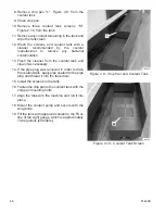
2. Remove cover “A”, Figure 2.1, to gain access to the grease manifolds and grease lines.
3. Jog each axis until the grease/lubrication lines are accessible.
4. Power down and lock out the machine. Refer to the appropriate power-down procedure in
Chapter 1.
- NOTE -
Replace the lubrication lines one line at a time.
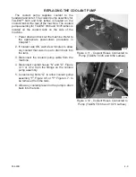
The ball screw lubrication lines connect to the middle fitting (marked “BS”) on each
grease manifold.
5. Check each lubrication line for damage. Before disconnecting the line being replaced, measure
the length and check the route from the grease manifold to either the linear guide or ball screw.
6. Disconnect the lubrication line and compare the length of the old lubrication line and the
replacement lubrication line.
7. Before installing the replacement line, fill the line with KLÜBER
®
Isoflex NCA 15 or NBU 15
grease.
8. Install the replacement lubrication line:
A) Connect one end of the replacement lubrication line at the grease manifold.
B) Add the specified grease through its fitting until grease appears at the other end of the
lubrication line.
C) Connect that end of the lubrication line.
9. Wipe the fittings clean of excess grease.
10. Install cover “A”, Figure 2.1.
11. Power up the machine. Refer to the appropriate power-up procedure in Chapter 1.
12. Jog the axes at 50% of the maximum rapid traverse for a full 30 minutes before resuming
automatic machine operation.
2-8
M-448B
Содержание Talent 10/78
Страница 9: ... NOTES M 448B vii ...
Страница 10: ... NOTES viii M 448B ...
Страница 17: ... NOTES M 448B 1 7 ...
Страница 18: ... NOTES 1 8 M 448B ...
Страница 27: ... NOTES M 448B 2 9 ...
Страница 28: ... NOTES 2 10 M 448B ...
Страница 32: ... NOTES 3 4 M 448B ...
Страница 43: ... NOTES M 448B 4 11 ...
Страница 44: ... NOTES 4 12 M 448B ...
Страница 49: ... NOTES M 448B 5 5 ...
Страница 50: ... NOTES 5 6 M 448B ...
Страница 61: ... NOTES M 448B 6 11 ...
Страница 62: ... NOTES 6 12 M 448B ...
Страница 65: ... NOTES M 448B A1 3 ...
Страница 66: ... NOTES A1 4 M 448B ...
Страница 68: ...A2 2 M 448B Figure A2 3 Coolant Pump Electrical Connection TALENT 6 45 and 8 52 Lathes TP6027 ...
Страница 73: ...M 448B A2 7 Figure A2 10 Tailstock Quill Hydraulic Valves TALENT 8 66 and 10 78 Lathes TP6040 ...
Страница 77: ...M 448B A2 11 Figure A2 15 Collet Closer and Tailstock Foot Switches TALENT 8 66 and 10 78 Lathes TP6025 ...
Страница 78: ...A2 12 M 448B Figure A2 16 Tailstock Hydraulic Valves TALENT 6 45 and 8 52 Lathes TP5240 ...
Страница 79: ...M 448B A2 13 Figure A2 17 Tailstock Hydraulic Valves TALENT 8 66 and 10 78 Lathes TP6045 ...
Страница 86: ...A2 20 M 448B Figure A2 24 Internal Power Case View Relay Panel TP5208A ...
Страница 91: ...M 448B A2 25 Figure A2 29 Internal Power Case View Service Entrance to Power Case TP5217A ...
Страница 92: ...A2 26 M 448B Figure A2 30 Internal Power Case View Fuse and Contactor Panel TP5209A ...
Страница 97: ...M 448B A2 31 Figure A2 35 Pump for Through Tool Coolant TP5231 ...
Страница 98: ...A2 32 M 448B Figure A2 36 Spindle with Chuck Removed TP5236 ...
Страница 99: ...M 448B A2 33 Figure A2 37 Spindle with Chuck Installed TP5243 ...
Страница 100: ...A2 34 M 448B Figure A2 38 Tailstock Assembly TALENT 6 45 6 45SV 8 52 and 8 52SV Lathes TP5754 ...
Страница 101: ...M 448B A2 35 Figure A2 39 Tailstock Assembly TALENT 8 66 and 10 78 Lathes TP6044 ...
Страница 102: ...A2 36 M 448B Figure A2 40 Z Axis Drive Motor TALENT 8 66 and 10 78 Lathes TP6049 ...
Страница 103: ... NOTES M 448B A2 37 ...
Страница 104: ...Hardinge Inc Elmira New York 14902 1507 USA Phone 607 734 2281 FAX 607 734 8819 www hardinge com ...


