background image

Page 16

For technical questions, please call 1-888-866-5797.

ITEM 59206 


SAFETY

SETU
p

Op
ERA
TION

M

AINTENANCE

CARBON MONOXIDE SHUTOFF

DANGER! TO pREVENT SERIOUS INJURY AND DEATH FROM CARBON MONOXIDE INHALATION: 

The Carbon Monoxide sensor is an additional layer of protection only.  Do not use the 

Generator in any area or situation that will allow carbon monoxide to accumulate.

•  FLASHING RED LIGHT: 

Dangerous levels of carbon monoxide gas 

have built up.  Leave immediately until 

area has aired out. Move Generator to 

well-ventilated area before operation.

•  FLASHING YELLOW LIGHT: 

Carbon monoxide sensor malfunction. 

Sensor needs service.  Call 1-888-866-5797 as 

soon as possible.  Do not use the Generator until 

the sensor is working properly.


NOTE: Yellow light flashes once 

after starting to indicate passing self-

check and is functioning normally.

Carbon Monoxide sensor must only be serviced by qualified technician to restore it to original settings.  Do 

not modify or tamper with the Carbon Monoxide sensor. Not following these instructions can result in death 

or serious injury due to Carbon Monoxide sensor malfunction.  


Connecting Electrical Loads

Familiarize yourself with the engine controls, power panel and how to start the engine before using the 

Generator. Calculate the wattage of the products you will use with the Generator and verify that the Generator 

can handle the total load. 

WARNING!  

Connect only properly wired plugs 

to the Generator.  A plug that is spliced onto a 

different cord may be hazardous.  Only a qualified 

electrician should wire a plug onto a cord. 

NOTICE:  

Never exceed the rated capacity for this Generator, 

as serious damage to the Generator and/or appliances, 

tools, and equipment could result from an overload.  Starting 

and running wattage requirements should always be 

calculated when matching this Generator’s wattage capacity to the appliance, tool, or equipment.

Use the DC12 V Receptacle to power 12 VDC equipment. 

WARNING! 

Do not charge batteries without a proper charge controller.  Do not overcharge.

a.  Connect the items that require the most wattage first.
b.  Connect “inductive” load appliances, tools, and equipment next.  Inductive 

loads are small hand tools and some small appliances.  

c.  Connect any lights next.
d.  Voltage sensitive appliances, tools, and equipment should be the last to be connected to the Generator.  

Plug voltage sensitive items such as TVs, DVD players, microwaves, and cordless telephones into a UL

®


Listed voltage surge protector (not included).  Then, connect the surge protector into the Generator.

IMpORTANT!

  Failure to connect and operate appliances, tools, and equipment in this sequence can cause 

damage to the Generator, appliances, tools, and equipment and will 

void 

the Warranty of this Generator.

Note:  

If Engine speed or voltage fluctuates with a load below the Generator’s 

running watts, move the Choke Lever to the halfway position.
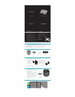
St

1,000

400

200  

1,200

Tota

l Ru

nnin

g W

atts


4,20

0

Larg

est A

ddit

iona

l Sta

rt-up

 Wa

tts

1,200

artu

p Wa

tts n

eed

ed f

or a

ll lo

ads


5,40

0

Must be 

less than 

7,250

Must be 

less than 

9,000

Evenly distributed 

over outlets:

IF ANY CIRCUIT BREAKERS TRIp CHECK THE FOLLOWING:

1.  Make sure that 

ALL circuit breakers

 are reset 

before starting the Generator again.

2.  Adjust the plugs so the loads are  

shared across outlet circuits.

To achieve rated output from the Generator, 

distribute loads over outlets.

Содержание PREDATOR 59206

Страница 1: ...o do so can result in serious injury SAVE THIS MANUAL Visit our website at http www harborfreight com Email our technical support at productsupport harborfreight com Email our engine support at predat...

Страница 2: ...e use of a special tool or lock and key or other means of security and shall be controlled by the authority responsible for the location 2 Gasoline fuel and fumes are flammable and potentially explosi...

Страница 3: ...de sensor malfunction Sensor needs service Do not use the Generator until the sensor is working properly For technical questions please call 1 888 866 5797 NOTE Yellow light flashes once after startin...

Страница 4: ...re the Generator on transport vehicles to prevent the tool from rolling slipping and tilting 23 Industrial applications must follow OSHA requirements 24 Do not leave the Generator unattended when it i...

Страница 5: ...ion Do not modify the generator or its engine and do not use the generator for a purpose for which it is not intended 43 Extension Cord Make sure your extension cord is in good condition When using an...

Страница 6: ...rrectly 9 Store equipment out of the reach of children 10 Follow scheduled engine and equipment maintenance GFCI Protection This Generator is equipped with two 3 Prong duplex 120V ground fault circuit...

Страница 7: ...ne Recommended fill level 8 Gallons Engine Oil Type SAE 10W 30 above 32 F 5W 30 at 32 F or below Capacity 1 16 Quart Spark Plug Type NHSP Torch F7TC Gap 0 028 0 031 Valve Clearance Intake 0 004 0 006...

Страница 8: ...volt or 240 volt that is compatible with the electrical characteristics and rated capacities of the tools and equipment being used 3 ON OFF Circuit Breakers The circuit breaker protects the Generator...

Страница 9: ...ended to power sensitive electronic equipment without the addition of an appropriate line conditioner and surge protector both not included Sensitive electronic equipment includes but is not limited t...

Страница 10: ...ns are as follows Use one of the following as the grounding electrode Pipe or conduit minimum in diameter minimum 8 ft long If steel it must have anti corrosion coating Rod stainless steel or copper o...

Страница 11: ...plate c Remove the nuts to allow the air cleaner housing to be moved aside Air Cleaner Housing Nuts Deflecting Plate Foam Filter Air Cleaner Cover 4 Place a bowl under the fuel cup to catch any spille...

Страница 12: ...questions please call 1 888 866 5797 ITEM 59206 Safety Setup Operation Maintenance High Altitude Kit Parts List A Part Description Qty 1a Main Jet 3000 6000 ft 1 2a Main Jet 6000 8000 ft 1 3a Bolt Sea...

Страница 13: ...t threading it in and remove it to check the oil level The oil level should be up to the full level as shown above 5 If the oil level is at or below the low mark add the appropriate type of oil until...

Страница 14: ...If above test fails do not use receptacle until it is repaired or replaced d Press Reset button in for use RESET TEST RESET TEST Reset Button Test Button 120 Volt GFCI Receptacle 4 Plug in products 5...

Страница 15: ...t the engine can stabilize For MANUAL START A Turn the Engine Switch to ON B Grip the Starter Handle of the Engine loosely and pull it slowly several times to allow the gasoline to flow into the Engin...

Страница 16: ...er exceed the rated capacity for this Generator as serious damage to the Generator and or appliances tools and equipment could result from an overload Starting and running wattage requirements should...

Страница 17: ...r that only supplies the exact watts needed To Calculate Wattage Volts and amps can be multiplied together to get watts volts x amps watts To Calculate Additional Start Up Watts If They Are Not Listed...

Страница 18: ...gine in an emergency turn the Engine Switch off NOTICE Generator shut off under load may damage the Generator and attached equipment Stopping the Engine Under Normal Conditions 1 Before turning off th...

Страница 19: ...qualified technician service the equipment instead Cleaning Maintenance and Lubrication Note This maintenance schedule is intended solely as a general guide If performance decreases or if equipment o...

Страница 20: ...Remove the drain plug and if possible tilt the crankcase slightly to help drain the oil out Recycle used oil 5 Replace the drain plug and tighten it 6 Clean the top of the Dipstick and the area around...

Страница 21: ...de the spark plug can be damaged 5 Install the new spark plug or the cleaned spark plug into the engine Gasket style Finger tighten until the gasket contacts the cylinder head then about 1 2 2 3 turn...

Страница 22: ...uretor and carefully remove the Drain Bolt from the bottom of the Carburetor Bowl allowing the fuel to drain completely Replace the Drain Bolt after draining WARNING To prevent serious injury and fire...

Страница 23: ...ilter IGNITION SPARK RELATED 1 Power Switch at OFF position 2 Spark plug cap not connected securely 3 Spark plug electrode wet or dirty 4 Incorrect spark plug gap 5 Spark plug cap broken 6 Circuit bre...

Страница 24: ...y operate generator outside 2 Carbon monoxide sensor malfunction Sensor needs service Call 1 888 866 5797 as soon as possible Do not use the Generator until the sensor is working properly 3 Make sure...

Страница 25: ...er Plug in product and turn on 3 Turn off and unplug product Test GFCI receptacle If functioning properly reset GFCI plug in product and turn on 4 Have product repaired Product begins to operate abnor...

Страница 26: ...ASSEMBLY DIAGRAM IN THIS MANUAL AS A REFERENCE TOOL ONLY NEITHER THE MANUFACTURER OR DISTRIBUTOR MAKES ANY REPRESENTATION OR WARRANTY OF ANY KIND TO THE BUYER THAT HE OR SHE IS QUALIFIED TO MAKE ANY...

Страница 27: ...l Series 2 52 Wire Clip 1 53 Coil Subassembly Charge 1 54 Hex Socket Flange Face Bolt Small Series 2 55 Coil Ignition 1 56 Bolt 2 Part Description Qty 57 Clamp Charge Coil 1 58 Hex Socket Flange Face...

Страница 28: ...amp 1 141 Pipe Clamp 1 142 Pipe Clamp 1 143 Tube Fuel 1 144 Jacket Rubber 1 145 Cock Assy Fuel 1 146 Bolt 2 147 Crosspiece Subassembly 1 Part Description Qty 148 Bolt 1 149 Support Atr Cleaner 1 150 S...

Страница 29: ...64 65 66 67 67 68 68 69 70 71 72 71 74 75 76 78 77 73 80 82 83 84 79 81 85 86 87 88 89 90 91 92 93 94 95 96 97 98 99 100 101 102 103 104 107 108 105 106 109 110 111 112 113 114 115 116 117 119 118 120...

Страница 30: ...the exclusion or limitation of incidental or consequential damages so the above limitation of exclusion may not apply to you THIS WARRANTY IS EXPRESSLY IN LIEU OF ALL OTHER WARRANTIES EXPRESS OR IMPLI...

Страница 31: ...of components of the emissions control system and are covered by this two 2 year warranty For a full list of emissions control components covered by this warranty please see 40 CFR 1068 Appendix I 1...

Страница 32: ...26677 Agoura Road Calabasas CA 91302 1 888 866 5797...

Отзывы: