background image

Page 8

For technical questions, please call 1-800-520-0882.

Vertical Engine

Set Up

Model 68123

: The emission control system for this 

engine is warranted for standards set by the U.S. 

Environmental Protection Agency.  For warranty 

information, refer to the last pages of this manual. 

Models 68122: 

The emission control system for this 

Generator’s Engine is warranted for standards set by the 

U.S. Environmental Protection Agency and by the California 

Air Resources Board (also known as CARB).  For warranty 

information, refer to the last pages of this manual.

Read the ENTIRE IMPORTANT SAFETY 

INFORMATION section at the beginning 

of this manual including all text 

under subheadings therein before 

set up or use of this product.

TO PREVENT SERIOUS INJURY: 

Operate only with proper spark arrestor installed.
Operation of this equipment may create sparks that 

can start fires around dry vegetation. 

A spark arrestor may be required. 

The operator should contact local fire agencies for laws 

or regulations relating to fire prevention requirements.

At high altitudes, the engine’s carburetor, governor (if so 

equipped), and any other parts that control the fuel-air 

ratio will need to be adjusted by a qualified mechanic to 

allow efficient high-altitude use and to prevent damage to 

the engine and any other devices used with this product.
1. 

IMPORTANT:  

If you have any doubts about your 

ability to perform the following procedures, have a 

qualified service technician perform the installation.

2.  Install this engine on a lawn mower only.
3.  Set the Engine upright on the mower, and align at 

least three 3/8” diameter coarse threaded engine 

mounting holes with mower mounting holes.

NOTE:  

Depending on the mower, it may be necessary 

to drill mounting holes or make a mounting plate 

to align with the engine mounting holes.  Only a 

qualified technician should attempt these solutions.

4.  Use 3/8” diameter, coarse threaded, hardened, 

stainless steel Bolts, Lock Washers, and Washers (not 

included) of appropriate length to secure the Engine to 

the mower.   

Make sure the hardware does not 

contact moving parts.

5.  Insert the mower’s brake cable sheath through the 

hole in the Brake bracket.  Secure the mower brake 

cable to the brake arm.  Adjust the brake cable sheath 

to remove all slack and secure it in place using the 

adjusting nuts on the cable sheath, as shown in the 

illustration below.


THE ENGINE BRAKE IS FOR EMERGENCY 

SHUTOFF; DO NOT REPLACE THE BRAKE SPRING 

WITH A WEAKER SPRING.  If operating the engine 

brake is too difficult, a qualified technician must 

install a different brake handle on the mower.

Note:

  The brake cable on some mowers may 

need to be adjusted in a different manner.  Install 

according to mower manufacturer’s instructions.

6. 

Brake 

Arm

Choke

Brake 

Cable

Brake 

Cable 

Bracket

Choke 

Cable

Bracket 

and 

Bolt

Attach the end of the mower’s Choke Cable 

to the Choke.  Use the Bracket and Bolt to 

secure its sheath in place as shown above.

7.  This engine is set to a single speed 

that should not be adjusted.

8.  Refer to the mower’s service manual for instructions 

on how to properly attach a belt drive pulley, chain 

drive gear, etc. onto the output shaft of the Engine.

Содержание 68122

Страница 1: ...mber Location on page 7 Note If product has no serial number record month and year of purchase instead Note Some parts are listed and shown for illustration purposes only and are not available individ...

Страница 2: ...Capacity 0 6 Quart Run Time 50 Load with full tank 40 minutes Sound Level 104 dB Bore x Stroke 70 mm x 45 mm Displacement 173cc Compression Ratio 8 5 1 Rotation viewed from PTO power takeoff the outpu...

Страница 3: ...oderate injury NOTICE is used to address practices not related to personal injury CAUTION without the safety alert symbol is used to address practices not related to personal injury Symbol Definitions...

Страница 4: ...ors and vents 2 Keep children away from the equipment especially while it is operating 3 Keep all spectators at least six feet from the Engine during operation 4 Fire Hazard Do not fill gas tank while...

Страница 5: ...nts get very hot during use Stay clear of hot parts 21 Do not cover the engine or equipment during operation 22 Keep the equipment engine and surrounding area clean at all times 23 Use the equipment a...

Страница 6: ...rbor Freight Tools for a replacement 6 Have the equipment serviced by a qualified repair person using only identical replacement parts This will ensure that the safety of the equipment is maintained D...

Страница 7: ...l questions please call 1 800 520 0882 Vertical Engine Engine Components Starter Handle Priming Bulb Brake Arm Choke Air Filter Muffler Fuel Cap Dipstick XXXXXXXXXX Serial Number Location Write on fro...

Страница 8: ...on 2 Install this engine on a lawn mower only 3 Set the Engine upright on the mower and align at least three 3 8 diameter coarse threaded engine mounting holes with mower mounting holes NOTE Depending...

Страница 9: ...The SAE Viscosity Grade chart on page 13 in the Service section shows other viscosities to use in different average temperatures 5 Thread the Dipstick back in clockwise CAUTION Do not run the engine w...

Страница 10: ...may be difficult to start on grass 1 Press the Priming Bulb 2 3 times to prime the engine 2 If the engine is cold adjust the Mower s choke control to the CHOKE START CLOSED position Note Location ope...

Страница 11: ...EN position NOTE Moving the Choke Lever too fast could stall the engine IMPORTANT Allow the engine to run at no load for a minute or two with no load after each start up so that the engine can stabili...

Страница 12: ...nce and Lubrication Schedule Note This maintenance schedule is intended solely as a general guide If performance decreases or if equipment operates unusually check systems immediately The maintenance...

Страница 13: ...to allow all the oil to drain out Recycle used oil 4 Wipe off the dipstick with a clean lint free rag 5 Add the appropriate type of oil until the oil level is at the full level SAE 10W 30 oil is reco...

Страница 14: ...torage as follows 1 CLEANING Wait for engine to cool then clean engine with dry cloth NOTICE Do not clean using water The water will gradually enter the engine and cause rust damage Apply a thin coat...

Страница 15: ...dle several times to air out the chamber Reinstall spark plug and set Choke to CHOKE START CLOSED position IGNITION SPARK RELATED 1 Spark plug cap not connected securely 2 Spark plug electrode wet or...

Страница 16: ...fuel tank with fresh 87 octane unleaded gasoline 3 Test replace fuel tank cap 4 Have qualified technician service magneto 5 Secure spark plug cap Engine stops when under heavy load 1 Dirty air filter...

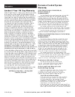
Страница 17: ...nition engines certified for model year 1997 and later must be designed built and equipped to meet the stringent anti smog standards set forth by the EPA HFT must warrant the emission control system o...

Страница 18: ...y part which fails malfunctions or is damaged due to failure to follow the maintenance and operating instructions set forth in the Owner s Manual including but not limited to a Use of parts which are...

Страница 19: ...800 520 0882 Vertical Engine Mounting Hole Diagram Note Not to scale A A 2 1 0 98 in 25mm 1 1 in 28mm 8mm A A A A 6 0 35 in 9mm 0 24 in 6mm 3 27 in 83mm 0 34 in 8 7mm 1 in 25 4mm 0 24 in 6mm 0 34 in...

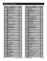
Страница 20: ...e Adjusting 2 55 Seat Valve Spring 2 56 Rocker Valve 2 57 Spring Valve 2 58 Guide Seal 1 59 Bolt Valve Adjusting 2 60 Valve Intake 1 Part Description Qty 61 Plate Asm Lifter Stopper 1 62 Lifter Valve...

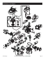
Страница 21: ...55 57 53 53 54 54 56 56 59 59 61 62 62 63 63 35 36 37 38 39 40 42 42 36 41 42 42 42 42 44 69 69 69 68 70 71 70 72 73 74 75 74 77 76 78 107 108 109 110 111 105 106 115 119 114 112 116 113 117 118 120...

Страница 22: ...Piston 1 49 Rod Connecting 1 50 Crankshaft Asm 1 51 Nut Valve Lock 2 52 Nut Valve Adjusting 2 53 Seat Valve Spring 2 54 Rocker Valve 2 Part Description Qty 55 Spring Valve 2 56 Guide Seal 1 57 Bolt Va...

Страница 23: ...45 47 64 62 63 55 58 56 53 53 55 51 51 52 52 54 54 57 57 59 60 60 61 61 33 34 35 36 37 38 40 40 34 39 40 40 40 40 42 67 67 67 66 68 69 68 70 71 72 73 72 75 74 76 96 97 98 99 100 94 95 104 108 103 101...

Страница 24: ...3491 Mission Oaks Blvd PO Box 6009 Camarillo CA 93011 800 520 0882 www harborfreight com...

Отзывы: