background image

1.

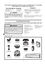
Check to see that you have received the following parts:

NOTE: If you are uncertain of part description, refer to
exploded view illustration.

4

Unpacking Instructions

For your convenience, check-off boxes are provided next to each step. As each step is completed, place a check
mark in the box. This will insure that all steps have been completed and will be helpful in finding your place should
you be interrupted.

an

otor

sse

ly

anger

racket

sse

ly

ownrod

anger

all

sse

ly

 Ceiling Canopy
 Canopy  crew Cover  sse

ly

otor Coupling Cover  sse

ly

ardware ags:

ire Connectors

Ceiling Canopy

Hanger Bracket

Assembly

Hardware Bags

Blade Set

This manual is designed to make it as easy as possible for you to assemble,

install, operate and maintain your ceiling fan

Tools Needed for Assembly

nstalled

ire ength

ire

i e

Before assembling your ceiling fan, refer to section
on proper method of wiring your fan (page 10). If you


feel you do not have enough wiring knowledge or
experience, have your fan installed by a licensed
electrician.

WARNING

!

p to 

 ft

 ft

Materials

iring outlet  o  and  o  connectors  ust e of type 

re uired y the local code

he

ini u  wire would  e a

conductor

wire with ground  of the following si e:

NOTE:

Place the parts from the loose parts bags in a small

container to keep them from being lost. If any parts are
missing contact your local retailer.

Motor Coupling

Cover Assembly

Light Plate/Glass Assembly

Fan Motor Assembly

lade

et

Downrod/

Hanger Ball Assembly

Canopy Screw

Cover Assembly 

‡

 Light Plate/Glass Assembly

‡/('$VVHPEO\

‡+DQG+HOG5HPRWH
‡5HFHLYHU8QLW

‡

One Phillips head screwdriver

‡

One stepladder

‡

Three wire connectors

‡

One wire stripper

‡

One 1/4” blade

screwdriver

Ý6HDG6FUHZV

6WDLQOHVV)ODW:DVKHUV

Hand-held 
Remote

Receiver
Unit

LED Assembly

Do not install or use fan if any part is damaged or
missing. This product is designed to use only those
parts supplied with this product and/or any
accessories designated specifically for use with this
product by 

us

. Substitution of parts or

accessories not designated for use with this product
by 

us

 could result in personal injury or property 

damage.

Содержание Teolo

Страница 1: ...19 CEILING FAN Serial Number Purchase Date Net Weight 21 23 lbs 9 63 kg Questions problems missing parts Before returning to your retailer call our customer service department READ AND SAVE THESE INS...

Страница 2: ...e within one year after original purchase due to a defect in materials or workmanship we will repair or replace at our option the defective part free of charge for parts and labor performed at our nat...

Страница 3: ...ing Fan 7 How to Hang Your Ceiling Fan 9 How to Wire Your Ceiling Fan How to Install Your Canopy Housing How to Assemble Your Ceiling Fan Blades How to Assemble Your Light Kit How to Operate Your Ceil...

Страница 4: ...edge or experience have your fan installed by a licensed electrician WARNING p to ft ft Materials iring outlet o and o connectors ust e of type re uired y the local code he ini u wire would e a conduc...

Страница 5: ...volts AC 60 HZ 15 Amp Circuit Electrical code requires use of a fan rated outlet box to support the extra weight and motion associated with a ceiling fan A fan rated box will be labeled as such and t...

Страница 6: ...reduce the risk of fire electrical shock or personal injury mount fan to outlet box marked acceptable for fan support of 15 88 kg 35 lbs or less Use screws supplied with outlet box Most outlet boxes...

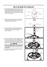
Страница 7: ...pin with hairpin clip Tighten the two set screws with nuts in the downrod support Figure 4 WARNING It is critical that the clevis pin in the downrod support is properly installed and the set screws an...

Страница 8: ...canopy Figure 7 Route the black white and blue wires through the hanger ball Position the pin through the two holes in the downrod and align the hanger ball so the pin is captured in the groove in th...

Страница 9: ...between the hanger ball assembly and the hanger bracket 1 Securely attach the hanger bracket to the outlet box not included using the outlet box screws and washers supplied with the outlet box Figure...

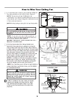
Страница 10: ...leads upward and carefully push leads into the outlet box with the white and green leads to one side of the box and the black leads to the other side Figure 4 CAUTION INCORRECT WIRE CONNECTION WILL D...

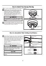
Страница 11: ...e electrical wires are completely inside the canopy housing and not pinched between the housing and the ceiling NOTE This step is applicable after the neccessary wiring is completed Canopy Screw Cover...

Страница 12: ...inside the adaptor plate at the bottom of the motor assembly Slightly loosen the remaining two screws Assemble the light plate assembly to the adaptor plate of the motor assembly using the two keyslot...

Страница 13: ...To make fan operational install 23A 12V battery included in hand held remote transmitter with fan power off Then follow the remote code setting process If not used for long periods of time remove batt...

Страница 14: ...or harsh rags which can warp and ruin the finish 1 Periodic cleaning of your new ceiling fan is the only maintenance that is needed When cleaning use only a soft brush or lint free cloth to avoids cr...

Страница 15: ...hed to fan 2 Loose screws in motor housing 4 Wire connectors inside housing rattling 5 Motor noise caused by solid state variable speed control 3 FAN WOBBLES EXCESSIVELY 1 Tighten both setscrews secur...

Страница 16: ...Insert FINISH CODES Refer to fan model number located on downrod support Reference Description 1 2 3 4 Motor Coupling Cover Assembly 5 Light Plate Glass Assembly LED Assembly Blade Set Receiver Unit H...

Страница 17: ...7 NOTE The illustration shown is not to scale or its actual con guration may vary Product parts are subject to change without notice Figure 1 12 12 1 12 2 3 4 5 6 9 7 8 10 11 Exploded View Illustratio...

Страница 18: ...TAS INSTRUCCIONES N mero de serie Fecha de compra Peso neto 9 63 kg 21 23 lbs VENTILADOR DE TECHO Preguntas problemas piezas faltantes Antes de volver a la tienda llame a nuestro Departamento de Servi...

Страница 19: ...icista calificado Las aspas del ventilador deben instalarse por lo menos a 2 13 m 7 pies del suelo a fin de evitar un contacto accidental con las mismas 4 Siga las recomendaciones sobre el m todo corr...

Страница 20: ...n contacto con su proveedor local Materiales tama o del cable seg n el A W G Calibre de Alambre Estadounidense longitud del cable instalado 14 12 hasta 15 2 m 50 pies de 15 2 a 30 5 m 50 a 100 pies Cu...

Страница 21: ...epresentamosalgunassugerencias para asegurar un rendimiento eficiente del producto Apague el ventilador cuando no se encuentre en la habitaci n Los ventiladores son para refrescar a la gente no a las...

Страница 22: ...pagar el interruptor de pared no es suficiente Para evitar posibles descargas el ctricas aseg rese de que la electricidad est desconectada en la caja de fusibles principal antes de realizar la instala...

Страница 23: ...soporte para techo a trav s de la varilla Figura 3 4 Enrosque el soporte de la varilla y alinee los orificios 5 Retire los dos tornillos en el ensamble del motor y gu rdelos para despu s Figura 5 de...

Страница 24: ...a extremo del cable Figura 9 NOTA Se deben revisar todos los tornillos de fijaci n y volver a ajustarlos cuando sea necesario antes de realizar la instalaci n 8 Vuelva a colocar la semiesfera en el ba...

Страница 25: ...olgar y la abrazadera para colgar ADVERTENCIA ADVERTENCIA Para evitar una posible descarga el ctrica aseg rese de cortar la alimentaci n el ctrica de la caja de fusibles principal antes de colgar el v...

Страница 26: ...el ventilador con el conector de cables incluido con la unidad receptora Conecte el conductor negro de la unidad receptora marcado TO MOTOR L al conductor negro del ventilador con el conector de cable...

Страница 27: ...Figura 1 ADVERTENCIA 2 Coloque y ajuste firmemente la cubierta para el tornillo de la base sobre los tornillos de reborde de la abrazadera para colgar mediante el mecanismo de seguro por giro del chav...

Страница 28: ...apriete tres los tornillos Figura 1 2 Retire uno de los tres tornillos en del ensamble de 3 Afloje levemente los otros dos tornillos Instale el conector 2 de pasadores desde unidad de luz LED conexi...

Страница 29: ...idad del mando a distancia del ventilador de techo C mo utilizar su ventilador de techo 3 Para que el ventilador sea functional instale las pila continuaci n siga el proceso de fijaci n remota de c di...

Страница 30: ...ventilador y la iluminaci n se apagar n tras 6 hora Enciende el ventilador y aumenta la velocidad Enciende el ventilador y disminuye la velocidad Enciende el ventilador y aumenta la velocidad 6 Si des...

Страница 31: ...mero Limpieza de las aspas Evite usar agua productos de limpieza o trapos speros que pueden combar o da ar las aspas Mantenimiento El nico mantenimiento necesario para el ventilador de techo es una li...

Страница 32: ...on recomendables Escoja un m todo de control alternativo 3 EL VENTILADOR OSCILA EN EXCESO 1 El tornillo de fijaci n y la tuerca del soporte de barral est n flojos 2 El tornillo de fijaci n en la unida...

Страница 33: ...or P ngase en contacto con su tienda para obtener las piezas de repuesto 1 2 3 4 5 Ensamble de la placa de iluminaci n vidrio Juego de aspas Unidad del receptor Mano a distancia 6 7 8 9 10 11 12 Unida...

Страница 34: ...NOTA Figura 1 36 12 12 1 12 2 3 4 5 6 9 7 8 10 11 Ilustraci n del despiece...

Отзывы: