background image

35

4

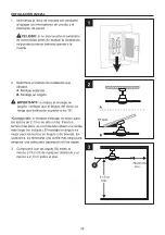
Mientras sostiene el kit de luces LED de 20 

W (I) debajo del ensamblaje del motor del 

ventilador (F), enganche los enchufes de la 

conexión de los cables:

Blanco con blanco

Negro con negro

Coloque las muescas en el borde interior del 

kit de luces LED de 20 W (I) de modo que 

coincidan con las pestañas en el exterior del 

borde de la placa de montaje del kit de luces. 

Levante con cuidado el kit de luces LED de 

20 W (I) dentro de la placa de montaje del kit 

de luces y gírelo en dirección de las 

manecillas del reloj para asegurarlo y que 

quede ajustado.


4.

INSTALACIÓN FINAL

Si no planea instalar el kit de iluminación con el 

ventilador en este momento, omita el paso 4 y 

continúe con el siguiente.

I

F

Enchufes 

de la conexión 

de cables

Muescas

Placa de montaje 

del kit de luces

Lengüetas

       PRECAUCIÓN: 

antes de comenzar la 

instalación, desconecte la alimentación 

colocando el interruptor de circuito en la posición 

de apagado o retirando el fusible de la caja de 

fusibles. No basta con colocar el interruptor del 

ventilador en la posición de apagado para evitar 

descargas eléctricas.

NOTA:

 si el kit de luces (I) se puede mover con 

la mano, significa que no se ha girado por 

completo hasta la posición correcta. Siga girando 

el kit de luces hasta que no moverlo con la mano.

Содержание FARMINGDALE AR15-72BN

Страница 1: ...20 5508794 5508785 5508793 HARBOR BREEZE and logo design are trademarks or registered trademarks of LF LLC All rights reserved Purchase Date Serial Number SS23783 Thank you for purchasing this HARBOR...

Страница 2: ...Contents Safety Information Preparation Initial Installation Fan Installation Wiring Final Installation Operating Instructions Care and Maintenance Troubleshooting Limited Lifetime Warranty Replacemen...

Страница 3: ...nopy D Downrod 1 A Mounting Bracket 1 C Canopy Bottom Cover 1 E Coupling Cover 1 1 F Fan motor Assembly 1 DESCRIPTION PART QUANTITY 5 G Blade I K H 5 J 1 Receiver Remote Pack 1 1 DESCRIPTION PART QUAN...

Страница 4: ...hich can be determined by turning the equipment off and on the user is encouraged to try to correct the interference by one or more of the following measures Reorient or relocate the receiving antenna...

Страница 5: ...n outlet box UL Listed acceptable for fan support of 35 lb 15 9 kg or less and use mounting screws provided with the outlet box Most outlet boxes commonly used for the support of lighting fixtures are...

Страница 6: ...AUTION Be sure outlet box is properly grounded and a ground wire green or bare is present After opening top of carton remove mounting hardware package from foam inserts Remove motor from packing and p...

Страница 7: ...s 7 ft high or higher For taller ceilings you may want to use a longer downrod not included Angle mounting is best suited for angled or vaulted ceilings A longer downrod is sometimes necessary to ensu...

Страница 8: ...g bracket A from the canopy B Secure mounting bracket A to outlet box not included using screws lock washers and flat washers provided with the outlet box NOTE It is very important you use the proper...

Страница 9: ...ocket is properly seated in the groove in the downrod D This will help to balance the ceiling fan Secure the safety cable to the building structure that independent to the outlet box using safety cabl...

Страница 10: ...t White wire AC in N White wire neutral From fan and receiver To outlet box Green yellow wire Green or bare wire ground There are two green grounding leads one from the mounting bracket one from the h...

Страница 11: ...s b Electrical rating 120V 60 Hz motor amps 1 5 MAX Should you choose to use a different remote control with this fan it must also meet these same requirements 3 2 Wrap electrical tape not included ar...

Страница 12: ...B clockwise until it locks in place at the narrow section of the key holes Make sure the positioning pin on the mounting bracket falls into one of two holes on the canopy B and then tighten the two c...

Страница 13: ...kit I clockwise until snug 4 FINAL INSTALLATION If you do not plan to install the light kit with your fan at this time skip step 4 and proceed to next step I F Wire Connection Plugs Notches Light Kit...

Страница 14: ...from the LED light kit I by use the flat blade screwdriver into the two holes on top of the LED light kit I 3 Remove the LED module plate from the light mounting kit by remove three screws on the ligh...

Страница 15: ...he decorative cover assembly so they match the tabs on the outside of the rim on the light kit mounting plate Carefully lift the decorative cover assembly inside the light kit mounting plate and secur...

Страница 16: ...es may explode or leak Do not mix old and new batteries Do not mix alkaline standard carbon zinc or rechargeable nickel cadmium batteries Exhausted batteries are to be removed from the product Non rec...

Страница 17: ...h in the battery compartment to the 1 position Turn the fan s AC power ON Within 30 seconds of turning AC power on press and release the LEARN button located in the remote s battery compartment to ent...

Страница 18: ...ction A downward air flow creates a cooling effect This allows you to set your air conditioner on a warmer setting without affecting your comfort 4B Cool weather Clockwise Direction An upward air flow...

Страница 19: ...eriodically Use only a soft brush or lint free cloth to avoid scratching the finish The plating is sealed with a lacquer to minimize discoloration or tarnishing IMPORTANT Shut off main power supply be...

Страница 20: ...screw on hanging ball is not tightened properly 1 Tighten all blade screws 2 Replace blade 3 Replace with an approved speed control device 4 Allow fan a break in period of a few days especially when...

Страница 21: ...t cover changes in brass finish rusting pitting tarnishing corroding or peeling Brass finish fans maintain their beauty when protected from varying weather conditions Any glass provided with this fan...

Страница 22: ...220 J 5508785 J 5508797 J 5508794 J 5508793 J 5508799 I 5660220 I 5508785 I 5508797 I 5508794 I 5508793 I 5508799 H 5660220 H 5508785 H 5508797 H 5508794 H 5508793 H 5508799 G 5660220 G 5508785 G 5508...

Страница 23: ...o del logotipo son marcas comerciales o marcas registradas de LF LLC Todos los derechos reservados Fecha de compra N mero de serie SS23783 Gracias por comprar este ventilador de techo HARBOR BREEZE P...

Страница 24: ...dad Preparaci n Instalaci n inicial Instalaci n del ventilador Cableado Instalaci n final Instrucciones de funcionamiento Cuidado y mantenimiento Soluci n de problemas Garant a limitada de por vida Li...

Страница 25: ...A Soporte de montaje 1 C Cubierta inferior de la base 1 E Cubierta del acoplador 1 1 F Ensamble del motor del ventilador 1 DESCRIPCI N PIEZA CANTIDAD 5 G Aspa I K H 5 J 1 Receptor paquete del control...

Страница 26: ...r al encender y apagar el equipo se recomienda al usuario que intente corregir la interferencia con una o m s de las siguientes medidas Reorientar o reubicar la antena de recepci n Aumentar la separac...

Страница 27: ...ener ventiladores de 15 90 kg 35 lb o menos y use los tornillos de montaje provistos con la caja de salida La mayor a de las cajas de salida que se utilizan com nmente para sostener las l mparas no so...

Страница 28: ...desnudo de puesta a tierra Despu s de abrir la parte superior de la caja retire el paquete de aditamentos de montaje de los accesorios de espuma Retire el motor del empaque y ub quelo sobre una alfom...

Страница 29: ...3 m de alto o m s Para los techos m s altos se recomienda utilizar una varilla m s larga no incluida El montaje en ngulo es mejor para los techos en ngulo o de b veda En ocasiones es necesaria una var...

Страница 30: ...Asegure el soporte de montaje A a la caja de salida no se incluye con los tornillos las arandelas de seguridad y las arandelas planas que incluye la caja de salida NOTA es muy importante que use los...

Страница 31: ...t bien asentada en la ranura de la varilla D Esto ayudar a equilibrar el ventilador de techo Asegure el cable de seguridad a la estructura de la construcci n que es independiente de la caja de salida...

Страница 32: ...e negro vivo Cable blanco CA en N Cable blanco neutro Del ventilador y A la caja de salida receptor Cable verde amarillo Cable verde o desnudo tierra Hay dos cables de conexi n a tierra verdes uno des...

Страница 33: ...e estado s lido b Clasificaci n el ctrica 120 V 60 Hz amperios del motor 1 50 m x Si utilizara otro control remoto con este ventilador tambi n debe cumplir estos mismos requisitos 3 2 Cubra con cinta...

Страница 34: ...cci n estrecha de los orificios principales Aseg rese de que el pasador de posicionamiento en el soporte de montaje caiga en uno de los dos orificios de la base B y luego apriete los dos tornillos de...

Страница 35: ...que quede ajustado 4 INSTALACI N FINAL Si no planea instalar el kit de iluminaci n con el ventilador en este momento omita el paso 4 y contin e con el siguiente I F Enchufes de la conexi n de cables...

Страница 36: ...ando el destornillador de punta plana en los dos orificios en la parte superior del kit de luz LED I 3 Quite los tres tornillos en el kit de montaje de la luz para retirar la placa del m dulo LED del...

Страница 37: ...de modo que coincidan con las pesta as en el exterior del borde de la placa de montaje del kit de la luz Levante con cuidado el ensamblaje de la cubierta decorativa dentro de la placa de montaje del...

Страница 38: ...n explotar o filtrarse No mezcle bater as antiguas con nuevas No mezcle pilas alcalinas est ndar carbono zinc o recargables n quel cadmio Las bater as agotadas se deben retirar del producto No deben r...

Страница 39: ...agn tico en el compartimiento de la bater a a la posici n 1 ENCIENDA la alimentaci n de CA del ventilador Dentro de los 30 segundos de encender la alimentaci n de CA presione y suelte el bot n LEARN u...

Страница 40: ...direcci n contraria a las manecillas del reloj Un flujo de aire descendente crea un efecto de enfriamiento Esto permite establecer el aire acondicionado en un ajuste m s c lido sin afectar la comodid...

Страница 41: ...ese de que est n aseguradas Debido al movimiento natural del ventilador algunas conexiones pueden soltarse con el tiempo No es necesario retirar el ventilador del techo Limpie el ventilador peri dicam...

Страница 42: ...t colocado firmemente 5 El ventilador est demasiado cerca del techo de b veda 6 El los tornillo s de fijaci n en la horquilla de la carcasa del motor no est n bien apretado s 7 El tornillo de fijaci n...

Страница 43: ...bilidad del comprador El distribuidor no asume ning n tipo de responsabilidad por la instalaci n del ventilador durante la garant a limitada de por vida Cualquier servicio realizado por una persona no...

Страница 44: ...5 A 5508797 A 5508794 A 5508793 A 5508799 J 5660220 J 5508785 J 5508797 J 5508794 J 5508793 J 5508799 I 5660220 I 5508785 I 5508797 I 5508794 I 5508793 I 5508799 H 5660220 H 5508785 H 5508797 H 550879...

Отзывы: