background image

9

1.

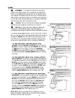
 Gently swing motor assembly (D) up to mounting 

plate (B), allowing slotted holes on plate at top of 
motor assembly (D) to align with loosened motor 
assembly mounting screws (FF) in mounting plate 
(B). Twist motor assembly (D) to lock. Re-insert 
motor assembly mounting screw (FF), along with 
lock washer (GG), that was previously removed 
(Step 3, page 7). Tighten all three motor assembly 
mounting screws (FF) securely. (Fig. 1)

FINAL INSTALLATION

1

2

3

IMPORTANT

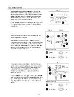
: Using a full range dimmer switch to 

control fan speed will cause a loud humming noise 
from fan. To reduce the risk of fire or electric shock, 
do NOT use a full range dimmer switch to control fan 
speed. (Fig. 3)

Dimmer 
Switch

Speed 
Switch

WIRING

2.

 Wrap electrical tape around each wire connector 

(EE) down to the wire as shown in Fig. 2.


Warning:

  Make sure no bare wire or wire 

strands are visible after making connections. Place 
green and white connections on opposite side of box 
from the black and blue (if applicable) connections.

Turn spliced/taped wires upward and gently push 
wires and wire connectors (EE) into outlet box.

N

EE

EE

EE

EE

Hardware Used

   E3 Wire Connector                               x 4 

Fig. 2

Fig. 3

Fig. 1

GG

FF

    Motor Assembly                                    x  3
    Mounting Screw

Hardware Used

    Lock Washer                                         x  3

For illustrative purposes only

--

not 

intended to cover all types of controls

B

GG

D

FF

Содержание CEDAR HILL

Страница 1: ...o your retailer call our customer service department at 1 800 527 1292 8 30 a m 5 p m CST Monday Friday ITEM 0312115 MODEL PEH44BCW5MC CEDAR HILL CEILING FAN espa ol p 17 Harbor Breeze is a registered...

Страница 2: ...Information 3 Package Contents 4 Hardware Contents 5 Preparation 6 Initial Installation 6 7 Wiring 8 9 Final Installation 9 12 Fan Operation 13 Care and Maintenance 13 Troubleshooting 14 Warranty 15...

Страница 3: ...box Most outlet boxes commonly used for the support of lighting fixtures are not acceptable for fan support and may need to be replaced Consult a qualified electrician if in doubt Secure the outlet bo...

Страница 4: ...ly 1 E Light Kit Fitter 1 F Glass Shade 1 G Blade Arm 5 H Blade 5 I Candelabra Base Bulb 3 J Pull Chain Extension in hardware pack 2 K Finial Plate pre attached to light kit fitter 1 L Finial pre atta...

Страница 5: ...Washer 10 in motor 11 1 in hardware pack Blade Washer in hardware pack 16 E3 Wire Connector in hardware pack 4 Motor Assembly Mounting Screw 3 pre attached in mounting plate Lock Washer for use with P...

Страница 6: ...port the full weight of the fan Failure to do this can result in serious injury or death The stability of the outlet box is essential in minimizing wobble and noise in the fan after installation is co...

Страница 7: ...at the top of the motor assembly D and slide it over the J hook on the mounting plate B to support the fan during wiring Fig 6 Hint Place square hole in motor assembly D over J hook in mounting plate...

Страница 8: ...l switch for the fan Connect BLUE wire from fan to the BLACK wire from the other independent wall switch for the light Connect WHITE wire from fan to WHITE wire from ceiling Connect all GROUND GREEN w...

Страница 9: ...educe the risk of fire or electric shock do NOT use a full range dimmer switch to control fan speed Fig 3 Dimmer Switch Speed Switch WIRING 2 Wrap electrical tape around each wire connector EE down to...

Страница 10: ...long with three blade washers DD to attach one blade arm G to a blade H Then tighten each blade screw BB starting with the one in the middle Fig 3 Repeat with remaining blades H 4 Insert two motor scr...

Страница 11: ...from threaded rod at top of light kit fitter E Remove finial L finial plate K and white washer from threaded rod at bottom of light kit fitter E Fig 6B Save hex nut HH lock washer II finial L finial...

Страница 12: ...hen you need to replace bulbs please allow bulbs and glass shade F to cool down before handling them Switch Housing 10 Place white washer that was removed in Step 6 of this section inside glass shade...

Страница 13: ...ed to turn the light ON or OFF Fig 2 3 Use the fan reverse switch located on the switch housing to optimize your fan for seasonal performance Fig 3 A ceiling fan will allow you to raise your thermosta...

Страница 14: ...bling 1 Blades H are loose 1 Tighten all blade screws BB 2 Blade arms G incorrectly 2 Re install blade arms G attached 3 Unbalanced blades H 3 Switch one blade H with a blade H from the opposite side...

Страница 15: ...conditions this warranty does not cover changes in brass finish rusting pitting tarnishing corroding or peeling Brass finish fans maintain their beauty when protected from varying weather conditions...

Страница 16: ...l our customer service department at 1 800 527 1292 8 30 a m 5 00 p m CST Monday Friday When ordering parts please have the Model or Item of the fan available which can be found on page 1 The followin...

Страница 17: ...Breeze es marca registrada de LF LLC Reservados todos los derechos Preguntas problemas faltan piezas Antes de regresar a la tienda llame o p ngase en contacto con nuestro departamento de servicio al c...

Страница 18: ...20 Contenido de art culos de ferreter a 21 Preparaci n 22 Instalaci n inicial 22 24 Conexi n de los cables 24 26 Instalaci n final 26 29 Funcionamiento del ventilador 30 Cuidado y mantenimiento 31 Lo...

Страница 19: ...las cajas de salida que se usan com nmente para sostener aparatos de alumbrado no son aceptables para sostener ventiladores y es posible que sea necesario reemplazarla Consulte con un electricista ca...

Страница 20: ...G Brazo para la paleta 5 H Paleta 5 I Bombilla de base candelabro 3 J Extensi n para la cadena de encendido 2 en paquete de art culos de ferreter a K Placa del adorno con rosca 1 sujetada de antemano...

Страница 21: ...en el paquete de art culos de ferreter a Arandela para la paleta 16 en el paquete de art culos de ferreter a Conector para cable E3 4 en paquete de art culos de ferreter a Tornillo para montaje de la...

Страница 22: ...ctura del edificio para que pueda sostener el peso total del ventilador El no hacer sto puede resultar en graves da os o la muerte La estabilidad de la caja de salida es esencial para minimizar tambal...

Страница 23: ...AA Tornillo del motor x 10 Arandela de seguridad 5 4 M M x 10 GG FF Tornillo para montaje x 3 de la unidad del motor Art culos de ferreter a que se usaron Arandela de seguridad x 3 2 Aseg rese de que...

Страница 24: ...tor para cable EE en el sentido de las agujas del reloj 1A VENTILADOR Y LUZ CONTROLADOS POR CADENAS DE ENCENDIDO Conecte el cable NEGRO y el AZUL del ventilador al cable NEGRO del techo Conecte el cab...

Страница 25: ...or y la placa de montaje al cable PELADO VERDE del techo Fig 1C Fig 1C Fig 1B BLANCO NEGRO INTERRUPTOR DE PARED INTERRUPTOR DE PARED para la LUZ NEGRO AZUL VENTILADOR VENTILADOR Y LUZ CONTROLADOS POR...

Страница 26: ...eros con ranura en la placa en la parte superior de la unidad del motor D se alineen con los tornillos para montaje de la unidad del motor FF aflojados en la placa de montaje B Gire la unidad del moto...

Страница 27: ...DD para sujetar un brazo para la paleta G a una paleta H Luego apriete cada tornillo para la paleta BB empezando con el de en medio Fig 3 Repita esto con las dem s paletas H CC AA Tornillo del motor...

Страница 28: ...dad II y la tuerca hexagonal HH Apriete la tuerca hexagonal HH encima de la arandela de seguridad II para lograr obtener un ajuste seguro Fig 7 Conecte el cable BLANCO del conectador para el juego de...

Страница 29: ...a pantalla de vidrio F Pase las cadenas de encendido por los agujeros correspondientes en la placa del adorno con rosca K y la cadena de encendido de en medio por el agujero en el adorno con rosca L A...

Страница 30: ...echo le permitir subir el termostato en verano y bajarlo en invierno sin notar una diferencia en su comodidad Nota Espere a que se detenga completamente el ventilador antes de usar el interruptor de r...

Страница 31: ...o un fusible inspeccione el fusible 3 Conexi n de cables defectuosa 3 Apague la electricidad Afloje el el bastidor del motor A e inspeccione todas las conexiones Funcionamiento ruidoso 1 Las paletas H...

Страница 32: ...de salida y si es necesario vuelva a conectarlos seg n las instruccion es en las p ginas 24 y 25 3 El interruptor de pared para el 3 Aseg rese de que el interruptor de ventilador est apagado de pared...

Страница 33: ...de condiciones clim ticas esta garant a no cubre ning n cambio en el acabado bronce ni por la oxidaci n marcas la decoloraci n la corrosi n ni el descascarillado del material Se conserva la belleza d...

Страница 34: ...ipci n A Bastidor del motor B Placa de montaje C Cubierta de la caja del interruptor E Conectador para el juego de luz F Pantalla de vidrio G Brazo para la paleta H Paleta J Extensi n para la cadena d...

Страница 35: ......

Страница 36: ......

Отзывы: