Harbor Breeze BELLHAVEN II E-BLHII52VPW5C4S Скачать руководство пользователя страница 29

29

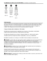
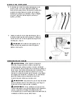
CONEXION DE LOS CABLES

4

1A

VENTILADOR Y LUZ CONTROLADOS POR 
CADENAS DE TIRO

NEGRO

BLANCO

DE PUESTA A TIERRA/VERDE (DESNUDO)

BLANCO

AZUL

BLANCO

DESDE EL VENTILADOR

Alimentación 
de 120 V 
DESDE 
EL 
TECHO

VENTILADOR

VERDE

NEGRO

VERDE

Escoja el diagrama de cableado (Fig. 1A, 
Fig. 1B o Fig. 1C) que se ajuste a su situación y 
realice las conexiones del cableado adecuadas 
como se indica a continuación: [

NOTA:

 Para 

cada conexión de cables a continuación, utilice 
uno de los conectores de cables (CC) provistos, 
asegurándose de atornillar el conector de cable 
(CC) en dirección de las manecillas del reloj].

 1. 

BLANCO

NEGRO

NEGRO (INTERRUPTOR DE PARED)

DE PUESTA A TIERRA/VERDE (DESNUDO)

NEGRO

AZUL

BLANCO

DESDE EL VENTILADOR

VENTILADOR

Alimentación 

de 120 V 

DESDE 

EL 

TECHO

VERDE

BLANCO

VERDE

1B

VENTILADOR CONTROLADO POR CADENA DE TIRO 
Y LUZ CONTROLADA POR INTERRUPTOR DE PARED

1B. 

VENTILADOR CONTROLADO POR 

CADENA DE TIRO Y LUZ CONTROLADA 
POR INTERRUPTOR DE PARED:

 Si desea 

controlar la luz del ventilador con un 
interruptor de pared separado, conecte el 
conductor 

NEGRO

 del ventilador con el 

conductor 

NEGRO

 del techo. Conecte el 

conductor 

AZUL

 del ventilador al conductor 

NEGRO

 del interruptor de pared 

independiente para la luz. Conecte el 
conductor 

BLANCO

 del ventilador al 

conductor 

BLANCO

 del techo. Conecte todos 

los conductores de 

PUESTA A TIERRA


(

VERDES

) juntos desde el ventilador (en la 

varilla (A) y soporte de montaje (C)) con el 
conductor 

DESNUDO

 o 

VERDE

 del techo. 

(Fig. 1B)

1A. 

VENTILADOR Y LUZ CONTROLADOS 

POR CADENAS DE TIRO:

 Conecte los 

conductores 

NEGRO

 y 

AZUL

 del ventilador 

al conductor 

NEGRO

 del techo. Conecte el 

conductor 

BLANCO

 del ventilador al 

conductor 

BLANCO

 del techo. Conecte todos 

los conductores de 

PUESTA A TIERRA


(

VERDES

) juntos desde el ventilador (en la 

varilla (A) y soporte de montaje (C)) con el 
conductor 

DESNUDO

 o 

VERDE

 del techo. 

(Fig. 1A)

Содержание BELLHAVEN II E-BLHII52VPW5C4S

Страница 1: ...erial Number Purchase Date 1 Federal regulations require ceiling fans with light kits manufactured or imported after January 1 2009 to limit total wattage consumed by the light kit to 190W Therefore t...

Страница 2: ...ed to be returned to the factory for repairs it must be shipped in its original packaging to ensure proper protection against damage that might exceed the initial cause for return Make sure that all e...

Страница 3: ...this fan are designed to accept only one 12 gauge house wire and two lead wires from the fan If your house wire is larger than 12 gauge or there is more than one house wire to connect to the two fan...

Страница 4: ...otor Housing 1 E Fitter Plate 1 F Yoke Cover 1 G Light Kit Fitter 1 H Blade Arm 5 I Blade 5 J Glass Shade 4 K Motor Screw 10 preassembled L Lock Washer 10 preassembled PART DESCRIPTION QUANTITY M Cano...

Страница 5: ...Required included 4 candelabra base 40 watt max bulbs DANGER When using an existing outlet box make sure the outlet box is securely attached to the building structure and can support the full weight o...

Страница 6: ...ious injury or death 1 2 Check to make sure blades I are at least 30 in from any obstruction Check downrod A length to ensure blades I are at least 7 ft above the floor Fig 3 3 ON OFF ON OFF 1 3 7 ft...

Страница 7: ...ceilings 8 ft 2 44 m high or higher For taller ceilings you may want to use a longer downrod not included than the one provided Angle style mounting is best suited for angled or vaulted ceilings A lon...

Страница 8: ...e cutters not included Fig 4 Note If you do not cut back the lead wires Steps 4 and 5 are not necessary and you may proceed to Step 6 instead FAN MOUNTING 8 Insert downrod A through canopy B canopy co...

Страница 9: ...e is present WARNING If house wires are different colors than referred to in the following steps stop immediately A professional electrician is recommended to determine wiring If you decided to cut ba...

Страница 10: ...with a separate wall switch connect BLACK wire from fan to BLACK wire from ceiling Connect BLUE wire from fan to the BLACK wire from the independent wall switch for the light Connect WHITE wire from...

Страница 11: ...cover T to the right clockwise until it stops Fig 1 T M B A A Wrap electrical tape not included around each individual wire connector CC down to the wire as shown in Fig 2 WARNING Make sure no bare wi...

Страница 12: ...lade I Then tighten each blade screw AA starting with the one in the middle Fig 2 Repeat with remaining blades I AA Blade Screw x15 Hardware Used BB Fiber Blade Washer x15 4 Partially loosen two motor...

Страница 13: ...emoved Fig 7 7 13 Connect male plug from motor housing D to female plug from light kit fitter G matching up the colors on the male plug with the colors on the female plug for correct fit Make sure plu...

Страница 14: ...ensions P supplied in one of the hardware packs or custom pull chain extensions not included may be attached to fan and light pull chains Fig 10 NOTE This fan is remote control adaptable remote contro...

Страница 15: ...is used to turn the lights ON or OFF Fig 2 3 Use the fan reverse switch located on the switch housing to optimize your fan for seasonal performance Fig 3 A ceiling fan will allow you to raise your the...

Страница 16: ...enance Do not use water or a damp cloth to clean the ceiling fan OPERATION INSTRUCTIONS CARE AND MAINTENANCE 3A 3B 3C 3C IMPORTANT Reverse switch must be set either completely LEFT or completely RIGHT...

Страница 17: ...um and High speeds Excessive wobbling 1 Blades I are loose 2 Blade arms H incorrectly attached 3 Unbalanced blades I 4 Fan not securely mounted 5 Fan too close to vaulted ceiling 6 Set screw s on moto...

Страница 18: ...purchase For the balance of the warranty call our customer service department at 1 800 527 1292 for return authorization and shipping instructions so that we may repair or replace the ceiling fan Any...

Страница 19: ...ilable which can be found on page 1 A E B F C G I H J L K M O N P R Q T AA BB CC PART DESCRIPTION A Downrod B Canopy C Mounting Bracket E Fitter Plate F Yoke Cover G Light Kit Fitter H Blade Arm I Bla...

Страница 20: ...a 5 00 p m hora central de lunes a viernes ADJUNTE SU RECIBO AQUI N mero de serie Fecha de compra El reglamento federal requiere que un ventilador de techo con juego de luz fabricado o importado despu...

Страница 21: ...brica por alguna reparaci n se debe enviar en su paquete original para asegurar la protecci n apropiada contra da os que podr an exceder la causa inicial por la cual se devolvi Aseg rese de que todas...

Страница 22: ...a aceptar s lo un cable de calibre 12 de la casa y dos cables principales del ventilador Si el calibre del cable de la casa es superior al 12 o hay m s de un cable de la casa para conectar a los cable...

Страница 23: ...Conectador para el juego 1 de luz H Brazo para la paleta 5 I Paleta 5 J Pantalla de vidrio 4 K Tornillo del motor 10 preensamblado L Arandela de seguridad 10 preensamblada PIEZA DESCRIPCON CANTIDAD M...

Страница 24: ...ctrica de h galo usted mismo disponible en Lowe s y cortaalambres Bombillas necesarias no se incluyen 4 bombillas de base candelabro de 40 vatios m x PELIGRO Cuando utilice una caja de salida existent...

Страница 25: ...1 2 Verifique que las paletas I est n alejadas al menos 76 20 cm de cualquier obstrucci n Verifique el largo de la varilla A para asegurarse de que las paletas I est n al menos a 2 13 m por encima de...

Страница 26: ...do para techos de 2 44 m o m s altos Para techos de mayor altura quiz s usted prefiera usar un v stago m s largo no incluido del provisto El montaje en ngulo es m s adecuado para techos en ngulo o abo...

Страница 27: ...e d al bastidor del motor D Pase los cables del bastidor del motor D por el v stago A Fig 2 Dependiendo del largo del v stago A que use es posible que tenga que cortar los cables principales para faci...

Страница 28: ...correctamente y que haya un conductor a tierra cable verde o pelado ADVERTENCIA Para reducir el riesgo de incendio choque el ctrico o da o corporal los conectores para cable provistos con este ventil...

Страница 29: ...LUZ CONTROLADA POR INTERRUPTOR DE PARED 1B VENTILADOR CONTROLADO POR CADENA DE TIRO Y LUZ CONTROLADA POR INTERRUPTOR DE PARED Si desea controlar la luz del ventilador con un interruptor de pared separ...

Страница 30: ...entro de la caja de salida CC Conector de cables E3 x4 2 2 1C VENTILADOR Y LUZ CONTROLADOS POR DOS INTERRUPTORES DE PARED BLANCO NEGRO INTERRUPTOR DE PARED NEGRO INTERRUPTOR DE PARED PARA LA LUZ DE PU...

Страница 31: ...localizado m s cerca del extremo abierto del soporte de montaje C Afloje parcialmente el otro tornillo para montaje de la cubierta M Eleve la cubierta B hasta el soporte de montaje C Ponga la parte re...

Страница 32: ...s para la paleta H para sujetar el brazo para la paleta H al motor Apriete bien los tornillos del motor K Fig 3 Repita esto con los dem s brazos para las paletas H asegur ndose de asegurar cada brazo...

Страница 33: ...uit anteriormente Fig 7 7 Conecte el enchufe macho del bastidor del motor D al enchufe hembra del conectador para el juego de luz G haciendo coincidir los colores en el enchufe macho con los del enchu...

Страница 34: ...las de vidrio J con los anillos del portal mpara Q Fig 8 Nota No apriete los anillos del portal mpara Q demasiado porque el vidrio se puede rajar o romper 8 Se pueden fijar las extensiones para las ca...

Страница 35: ...IONAMIENTO caja del interruptor La cadena de encendido etiquetada LUZ se usa para ENCENDER o APAGAR las luces Fig 2 Use el interruptor de reversa localizado en la caja del interruptor para optimizar e...

Страница 36: ...un pa o h medo para limpiar el ventilador CUIDADO Y MANTENIMIENTO 3A 3B 3C 3C IMPORTANTE El interruptor de reversa se debe configurar ya sea completamente HACIA LA IZQUIERDA o completamente HACIA LA...

Страница 37: ...ador es nuevo 1 Apriete todos los tornillos de las paletas AA 2 Remplace el paleta I 3 Reemplace por un dispositivo de control de velocidad autorizado 4 Permita que el ventilador tenga un per odo de a...

Страница 38: ...ueden poner bombillas en el ventilador que suman no m s de 190W Las luces se bajan al prender el ventilador y o las luces 1 Ponga bombillas en el juego de luz que suman no m s de 190W 1 Las bombillas...

Страница 39: ...pos de condiciones clim ticas esta garant a no cubre ning n cambio en el acabado bronce ni por la oxidaci n marcas la decoloraci n la corrosi n ni el descascarillado del material Se conserva la bellez...

Страница 40: ...20 Impreso en China PIEZA DESCRIPCION A V stago B Cubierta C Soporte de montaje E Placa de conexi n F Cubierta del yugo G Conectador para el juego de luz H Brazo para la paleta I Paleta J Pantalla de...

Отзывы: