

A
Outlet box
Screw
B
C
Canopy
6
7
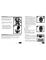
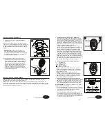
ASSEMBLY INSTRUCTIONS
ASSEMBLY INSTRUCTIONS
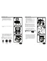
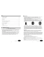
IMPORTANT:
Do NOT use this fan with a dimmer
switch or variable speed wall control. Using a dimmer
switch or variable speed wall control will damage the
fan.
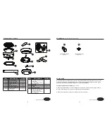
1. Attach mounting plate (A) to outlet box (not
included) using two screws (not included).
Securely tighten two outlet box screws. Pull
black, white, and grounded wires out of outlet
box and through the hole in the mounting plate
(A).
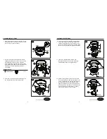
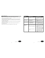
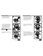
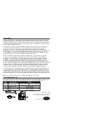
4. Connect the BLACK wire from the fan to the
BLACK wire from the ceiling.
Connect the WHITE wire from the fan, to the
WHITE wire from the ceiling.
Connect all GROUND (GREEN) wires from the
fan together to the GREEN/BARE wire from
ceiling.
Connecting the GREEN/GROUND wires is
conducive to receive the signal of the remote
control.
Note:
The BLACK wire is the hot power for the
fan and light kit. The WHITE wire is common for
fan and light kit. GREEN wire is the ground wire.
lf the household wires are different colors than
referred to above, stop immediately and consult a
professional electrician to determine proper wiring.
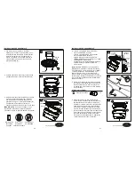
2. Place trim ring (C) over canopy, and lay it on fan
motor (B).
3. Loosen two preassembled screws across from
each other on the mounting plate (A). Remove
and save remaining two preassembled screws.
Hang fan motor (B) on mounting plate (A)
hook using one of the non-slotted holes in the
canopy.
6. Align keyhole slots on the fan motor (B) with the
protruding screw heads on the mounting plate
(A). Lift the fan motor (B) up to the mounting
plate (A), making sure not to break any wire
connections. Rotate the fan motor (B) clockwise
until the screw heads fully engage into keyhole
slots. Insert the previously removed screws
(Step 3, page 6) and securely tighten all the
screws.
Ground/
Green
White
Black
outlet box
black white green
white
GREEN/
GROUNDED
black
Supply circuit
receiver
Black
Black White Green
Outlet box
/
n
e
e
r
G
Ground
Receiver
White
4
2
1
5
3
6
ON
ON / OFF
switch
NO Variable
speed wall
control
NO Dimmer
switch
A
B
B
Canopy
Screw
Hook
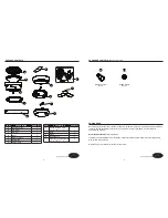
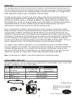
Hardware Used
5. Twist wire ends together and screw wire
connectors (AA) on in a clockwise direction.
Tape wire connectors (AA) and wires together
with electrical tape (not included).
x 4
Wire Connector
AA
Lowes.com/harborbreeze
Lowes.com/harborbreeze
Page 6
Page 7
AA
B
A
Screw


