

3
2
TABLE OF CONTENTS
Safety Information............................................................................................................... 2
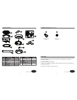
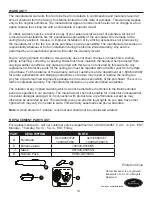
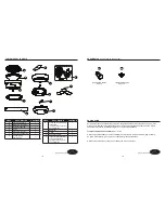
Package Contents............................................................................................................... 4
Hardware Contents...............................................................................................................5
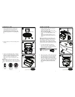
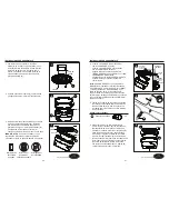
Preparation ......................................................................................................................... 5
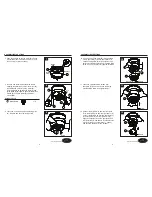
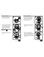
Assembly or Installation Instructions .................................................................................. 6
Operating Instructions ........................................................................................................ 10
Care and Maintenance ....................................................................................................... 12
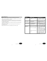
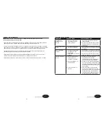
Troubleshooting................................................................................................................... 13
Warranty.............................................................................................................................. 14
Replacement Parts List ...................................................................................................... 14
SAFETY INFORMATION
WARNING
CAUTION
READ AND SAVE THESE INSTRUCTIONS
Please read and understand this entire manual before attempting to assemble, operate or install the
product.
• When using an existing outlet box, be sure the box is securely attached to the building structure
and can support the full weight of the fan, so to avoid potential serious injury or death.
• All wiring must be in accordance with the National Electrical Code “ANSI/NFPA 70” and local
electrical codes. Electrical installation should be performed by a qualified licensed electrician.
• DO NOT use bulbs with wattage greater than the maximum value stated on the fixture and in
this manual. Using a higher wattage bulb than specified will increase fixture temperature and
cause risk of fire.
• Disconnect the electrical supply circuit to the fan before installing kit.
• Electrical diagrams are for reference only.
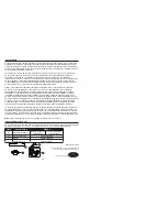
• The net weight of this fan including the light kit is: 15.62 lbs.
• ELECTRIC SHOCK HAZARD - To reduce the risk of electric shock, do not use this fan with
any solid-state speed control device.
• ELECTRIC SHOCK HAZARD - To reduce the risk of electric shock, make sure the electricity
has been turned off at the circuit breaker or fuse box before beginning installation.
• PERSONAL INJURY HAZARD - To reduce the risk of injury to persons, install fan so that the
blades are 7 ft. (2.1m) above the floor.
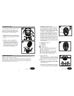
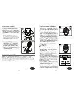
• ELECTRIC SHOCK HAZARD - Do not install this fan with variable speed wall control or
wall-mounted dimmer switch. It will permanently damage the fan’s remote control receiver and
cause the fan’s functions to fail.
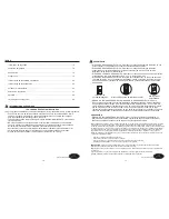
ON
ON / OFF switch
NO Variable speed wall control
NO Dimmer switch
• FIRE, ELECTRIC SHOCK OR PERSONAL INJURY HAZARD - To reduce the risk of fire,
electric shock, or personal injury, mount to an outlet box marked “ACCEPTABLE FOR FAN
SUPPORT OF 35.1 lbs OR LESS” and use the mounting screws provided with the outlet box.
Most outlet boxes commonly used for the support of lighting fixtures are not acceptable for
fan support and may need to be replaced. Consult a qualified licensed electrician if in doubt.
• PERSONAL INJURY HAZARD - To reduce the risk of personal injury, do not bend the blade
brackets when installing the brackets, balancing the blades, or cleaning the fan. DO NOT
insert foreign objects in between the rotating fan blades.
This equipment has been tested and found to comply with the limits for a Class B digital device, pursuant to Part 15 of
the FCC Rules. These limits are designed to provide reasonable protection against harmful interference in a residential
installation. This equipment generates, uses and can radiate radio frequency energy and, if not installed and used
in accordance with the instructions, may cause harmful interference to radio communications. However, there is no
guarantee that interference will not occur in a particular installation. If this equipment does cause harmful interference
to radio or television reception, which can be determined by turning the equipment off and on, the user is encouraged to
try to correct the interference by one or more of the following measures:
• Reorient or relocate the receiving antenna.
• Increase the separation between the equipment and receiver.
• Connect the equipment into an outlet on a circuit different from that to which the receiver is connected.
• Consult the dealer or an experienced radio/TV technician for help.
CAUTION:
Any changes or modifications not expressly approved by the grantee of this device could void the user’s
authority to operate the equipment.
This device complies with Part 15 of the FCC Rules. Operation is subject to the following two conditions:
(1) This device may not cause harmful interference, and (2) this device must accept any interference received, including
interference that may cause undesired operation.
Lowes.com/harborbreeze
Lowes.com/harborbreeze
Page 3
Page 2


