background image

FAN ALIGNMENT AND HANGER BRACKET INSTALLATION (Continued)

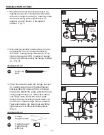
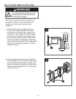
2. To begin mounting the hanger bracket (C), drill 
    a 1/4 in. pilot hole through the center of the 
    junction box, into the ceiling joist or structural 
    member, independent of the junction box. 
    Loosely attach the hanger bracket (C) to the 
    ceiling structure using the long lag bolt (HH) 
    and flat washer (EE). Do not fully tighten the 
    long lag bolt (HH) yet. Hanger bracket (C) 
    should be free to rotate. (Fig. 2)

Hardware Used

GG

x 1

EE

JJ

x 1

x 1

Steel
Washer 

Ceiling
Support Cable

Hardware Used

HH

x 1

Long Lag
Bolt

EE

x 1

Steel
Washer 

1. To attach ceiling support cable (JJ), drill a  
    1/4 in. pilot hole, located independently from 
    the junction box (not included), into the ceiling 
    joist or structural member. Securely attach the 
    ceiling support cable (JJ) with the short lag
    bolt (GG) and steel washer (EE). (Fig. 1)

WARNING

Failure to follow these hanger bracket 
installation procedures may result in 
damage to hanger bracket.

NOTE: Ceiling support cable must be fastened in 
the ceiling joists with 2 in. lag bolt.

JJ

EE

GG

1

NOTE: No lubrication to be used on screw. Pilot 
hole for lag screw to be no larger than 1/4 in 
diameter. Screw must have at least 1-1/2 in of 
thread engagement into structure joist.

2

C

EE

HH

1½ in.

Minimum

Short Lag
Bolt

10

Содержание 0196508

Страница 1: ...ll our customer service department at 1 888 567 2055 8 a m 5 p m EST Monday Friday Espa ol p 23 ITEM 0196508 MODEL LP8013LAZ MARICOPA CEILING FAN Harbor Breeze is a registered trademark of LF LLC All...

Страница 2: ...ignment and Hanger Bracket Installations Hanging Instructions Wiring Instructions Canopy Housing Installation Blade Installation Housing Switch Cup Adapter Assembly Installation Wall Control Wiring In...

Страница 3: ...alling Instructions for supply connections conductor of a fan identified as grounded conductor to be connected to a grounded conductor of power supply conductor of a fan identified for equipment groun...

Страница 4: ...SAFETY INFORMATION Continued The net weight of this fan is 36 6 lbs 16 6 kg This fan is to be used in dry or damp locations only WARNING 4...

Страница 5: ...U Q N O I T P I R C S E D T R A P A Motor Arm Assembly 1 B Switch Cup Assembly 2 1 t e k c a r B r e g n a H C D Downrod Hanger Ball Assembly E Ceiling Canopy 1 F Canopy Screw Cover 1 G Blade Holder A...

Страница 6: ...illips screwdriver 1 4 in flathead screwdriver wire stripper and step ladder Helpful Tools not included AC tester light do it yourself wiring handbook and wire cutters PREPARATION HARDWARE CONTENTS sh...

Страница 7: ...w in the hanger ball until the ball falls freely down the downrod Remove the pin from the downrod then remove the hanger ball Retain the pin and hanger ball for reinstallation in Step 4 Fig 1 1 D 2 Sl...

Страница 8: ...enter support housing of the motor arm assembly A until the downrod makes contact with the stop feature Align holes in downrod with holes in support housing Using the T handle wrench J secure downrod...

Страница 9: ...on the downrod as follows Route the three 54 in wires through the hanger ball Position the pin through the two holes in the downrod and align the hanger ball so the pin is captured in the groove in t...

Страница 10: ...x 1 Long Lag Bolt EE x 1 Steel Washer 1 To attach ceiling support cable JJ drill a 1 4 in pilot hole located independently from the junction box not included into the ceiling joist or structural memb...

Страница 11: ...ating the hanger bracket C Fig 2 3 Place fan assembly back into hanger bracket C making sure groove in downrod hanger ball assembly D mates with pin on hanger bracket C Attach the safety cable from fa...

Страница 12: ...ce as it must be grounded for safe operation Hardware Used II x 3 Wire Connectors 1 Connect the green grounding lead from the downrod hanger ball assembly D and the green grounding lead from the hange...

Страница 13: ...racket C Tighten shoulder screw Fully assemble and tighten second shoulder screw that was previously removed Fig 1 1 E CANOPY HOUSING INSTALLATION 2 Securely attach and tighten the canopy screw cover...

Страница 14: ...18 Hardware Used AA Screws x 12 x 18 2 Position the blade H over the blade holder G with threaded posts showing Make sure the bottom edge of the blade H is fully seated against the blade arm With a Ph...

Страница 15: ...slots in the switch cup assembly B Replace the third screw and securely tighten all three screws Fig 2 3 Securely attach the 9 pin switch cup connector to the wiring harness socket within the switch...

Страница 16: ...3 speed wall control I to black house supply hot Connect other black wire from 3 speed wall control I to black wire leading to outlet box Lastly connect green wire from 3 speed wall control I to grou...

Страница 17: ...l I to one of the numbered settings Fig 2 3 If airflow is desired in the opposite direction turn the fan off and wait for the blades to stop turning Then slide the reverse switch on each switch cup as...

Страница 18: ...he balancing clip in the balance kit LL to the top edge of the blade H near the blade holder arm of the motor assembly A Fig 2 Start the fan and notice wobble Stop the fan and move the balancing clip...

Страница 19: ...e finish CARE AND MAINTENANCE Fan will not start 1 Fuse or circuit breaker blown 2 Loose power line connections to the fan or loose switch wire connections in the switch housing 3 Loose connection at...

Страница 20: ...loose 3 Screws securing fan blade holders to motor hub are loose 4 Blade holders are not seated properly 5 Hanger bracket is not rigidly secured to a structural member 1 Tighten housing support bolts...

Страница 21: ...ishing corroding or peeling Brass finish fans maintain their beauty when protected from varying weather conditions Any glass provided with this fan is not covered by the warranty Any replacement of de...

Страница 22: ...er Arm Blade 3 Speed Wall Control T Handle Wrench Screw Washer Head Screw Fiber Washer Nylon Locking Nut Steel Washer Socket Head Cap Screw Short Lag Bolt Long Lag Bolt Wire Connectors Ceiling Support...

Страница 23: ...N mero de serie N mero de serie Harbor Breeze es una marca registrada de LF LLC Todos los derechos reservados Preguntas problemas piezas faltantes Antes de volver a la tienda llame a nuestro Departame...

Страница 24: ...nstrucciones para colgar Instrucciones de cableado Instalaci n de la carcasa de la base Instalaci n de las aspas Instalaci n del ensamble del adaptador soporte del interruptor de la carcasa Instruccio...

Страница 25: ...y su soporte deben ser capaces de sostener el peso del ventilador en movimiento como m nimo 15 88 kg NO use una caja de salida de pl stico Una vez instalado el ventilador aseg rese de que todas las co...

Страница 26: ...rcada como ACCEPTABLE FOR FAN SUPPORT APTA PARA SOPORTE DE VENTILADOR y use los tornillos de montaje que se proporcionan con la caja de salida La mayor a de las cajas de salida que se usan com nmente...

Страница 27: ...Abrazadera para colgar Ensamble de la bola para colgar varilla Escudo del techo Cubierta para los tornillo de la base Brazo de soporte del aspa Aspa Control de pared de 3 velocidades Llave con manija...

Страница 28: ...echo con tornillo Cant 1 KK Antes de comenzar a ensamblar el producto aseg rese de tener todas las piezas Compare las piezas con la lista del contenido del paquete y el diagrama anterior No intente en...

Страница 29: ...hasta que sta salga libremente de la varilla Retire el pasador de la varilla y luego retire la bola para colgar Guarde el pasador y la bola para colgar a fin de colocarlos nuevamente en el Paso 4 Fig...

Страница 30: ...ral del ensamble de brazo del motor A hasta que la varilla entre en contacto con la caracter stica de detenci n Alinee los orificios de la varilla con los orificios de la carcasa de soporte Use la lla...

Страница 31: ...r la bola para colgar en la varilla D como se indica Pase los tres cables de 137 16 cm de largo por la bola para colgar Coloque el pasador a trav s de los dos orificios de la varilla y alinee la bola...

Страница 32: ...colgar C a la estructura del techo con utilizando el tirafondo largo HH y una arandela plana EE No apriete completamente el tirafondo largo HH todav a La abrazadera para colgar C debe girar librement...

Страница 33: ...l ensamble del ventilador en la abrazadera para colgar C asegur ndose de que la ranura de la bola para colgar D coincida con el pasador de la abrazadera para colgar C Fije el cable de seguridad del ve...

Страница 34: ...te el conductor blanco del motor del ventilador al conductor blanco neutro mediante el conector provisto II de forma segura Conecte el conductor negro del motor del ventilador y el conector azul al co...

Страница 35: ...onexi n a tierra y que no haya conductores desnudos visibles en los conectores excepto el conductor con conexi n a tierra No opere el ventilador hasta que las aspas est n instaladas Podr a ocasionar r...

Страница 36: ...postes roscados que se muestran Aseg rese de que el borde inferior del aspa H est completamente asentado sobre el brazo del aspa Con un destornillador Phillips ajuste los tornillos con cabeza de aran...

Страница 37: ...mblados Fig 1 1 INSTALACI N DEL ENSAMBLE DEL ADAPTADOR SOPORTE DEL INTERRUPTOR DE LA CARCASA NOTA peri dicamente verifique los aditamentos de los soportes de las aspas y vuelva a asegurarlos si es nec...

Страница 38: ...colocar el tercer tornillo y ajuste firmemente los tres tornillos Fig 2 3 Ajuste firmemente el conector del soporte del interruptor de 9 clavijas al mazo de cables del portal mparas que se encuentra...

Страница 39: ...que va a la caja de salida Finalmente conecte el conductor verde del control de pared de 3 velocidades I al conductor de puesta a tierra que va a la caja de salida del techo Fig 1 2 Fije la unidad de...

Страница 40: ...e el flujo de aire corra en la direcci n opuesta apague el ventilador y espere hasta que las aspas dejen de girar Luego deslice el interruptor de reversa de cada ensamble de soporte del interruptor B...

Страница 41: ...a el ventilador y mueva el sujetador de equilibrio del kit de equilibrio LL a tramos peque os hacia el extremo del aspa H En cada tramo de incremento encienda el ventilador y observe el tambaleo Deter...

Страница 42: ...interruptor de circuito 2 Las conexiones de la l nea de alimentaci n el ctrica del ventilador o las conexiones del cable del interruptor en la carcasa del interruptor se han aflojado 3 Afloje la conex...

Страница 43: ...jan los soportes de las aspas del ventilador al eje del motor est n ajustados 4 Compruebe que los soportes de las aspas del ventilador est n firmes y uniformemente asentados en la superficie de la car...

Страница 44: ...descascaramiento Los ventiladores con acabado de lat n mantienen su belleza cuando se les protege de las cambiantes condiciones atmosf ricas La garant a no cubre los elementos de vidrio incluidos con...

Страница 45: ...tuerca de nailon Arandela de acero Tornillo de cabeza hueca Tirafondo corto Tirafondo largo Conectores de cable Cable del soporte de techo Abrazadera para el cable del soporte de techo con tornillo Ki...

Отзывы: