159
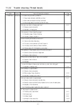
11-2-2 Trouble shooting (Thread break)
Trouble Factor Cause of trouble and measure Page
Thread break
Mechanical
1. Is needle drop unstable by vibration?
(2-2)
1-1 Reconsider where to install the machine.
1-2 Move the machine to floor fully reinforced.
1-3 Use strong table to be able to endure vibration.
2. No burr or scratch in thread guide hole?
3-1-1
2-1 Remove burr and scratch.
2-2 Replace of thread guide.
3. No problem in thread adjusting spring?
3-1-1
3-1 Replace spring if it doesn't spring.
3-2 If weak or broken, replace it.
4. Does detecting roller make smooth turn?
4-1 Clean inside hole of bearing.
4-2 Correct so as for slit disc not to touch sensor.
4-3 Correct so as for cable not to touch slit disc.
4-4 Check cable of TC 12 Board is unconnected
5. No problem in thread guide unit and thread tension ass’y?
3-1-1
5-1 Remove burr and scratch if appeared.
5-2 Remove lints and clean.
6. Does disc on thread tension ass’y. turn smoothly?
3-1-1
6-1 Remove lints and clean.
6-2 Replace
7. Is backlash between take-up lever and take-up crank roller not bigger?
7-1 Replace of take-up lever.
3-3-9
8. No problem in needle holder?
8-1 Remove burr and scratch.
8-2 Make proper fixing. (direction)
3-1-2
8-3 Replace if thread guide is bent.
3-1-1
9. No burr and scratch on needle plate?
3-1-1
9-1 Remove burr and scratch in needle hole.
9-2 Remove burr and scratch around needle hole on back of needle plate.
9-3 Replace it if not furbished.
9-4 If furbishing made needle hole wider, replace it.
10. No problem in pressure foot?
10-1 Remove burr and scratch.
3-1-1
10-2 Correct bent.
3-1-1
10-3 Adjust height.
3-3-6
10-4 Replace of pressure foot.
3-2-11
10-5 Replace of pressure foot drive cam.
3-2-4
Содержание HCD2-1501-40
Страница 1: ...Maintenance Manual for Embroidery Machine HCD2 1501 40 Version 2 3 HappyJapan Inc ...
Страница 10: ...10 HSA90311 Shell alvania EP Grease2 100g Page 31 33 36 M0404342 Needle height gauge Page 52 ...
Страница 150: ...143 10 1 Electrical connection diagram before Rev A for LCD CE board 1 3 ...
Страница 151: ...144 10 1 Electrical connection diagram before Rev A for LCD CE board 2 3 ...
Страница 152: ...145 10 1 Electrical connection diagram before Rev A for LCD CE board 3 3 ...
Страница 153: ...146 10 2 Electrical connection diagram before Rev A for LCD CE U LCD CE MX board 1 4 ...
Страница 154: ...147 10 2 Electrical connection diagram before Rev A for LCD CE U LCD CE MX board 2 4 ...
Страница 155: ...148 10 2 Electrical connection diagram before Rev A for LCD CE U LCD CE MX board 3 4 ...
Страница 156: ...149 10 2 Electrical connection diagram before Rev A for LCD CE U LCD CE MX board 4 4 ...
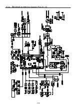
Страница 157: ...149a 10 2a Electrical connection diagram Rev A 1 4 ...
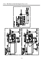
Страница 158: ...149b 10 2a Electrical connection diagram Rev A 2 4 ...
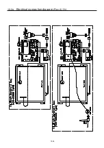
Страница 159: ...149c 10 2a Electrical connection diagram Rev A 3 4 ...
Страница 160: ...149d 10 2a Electrical connection diagram Rev A 4 4 ...
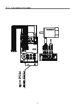
Страница 161: ...150 10 3 Connection of inverter Inverter set Inverter set ...
Страница 165: ...153 HCD8116 TP SW Circuit Board Ass y HCD8124 TC8 7 Circuit Board Ass y Rev A ...
Страница 166: ...154 HCD8119 y ...
Страница 198: ...2017 8 HappyJapan Inc 9 5 TAITO 2 CHOME TAITO KU TOKYO JAPAN TEL 81 3 3834 0711 FAX 81 3 3835 8917 ...

