135
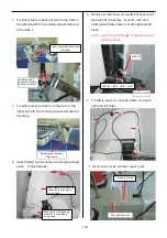
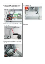
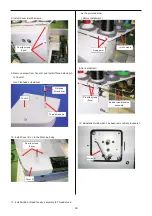
3.
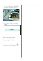
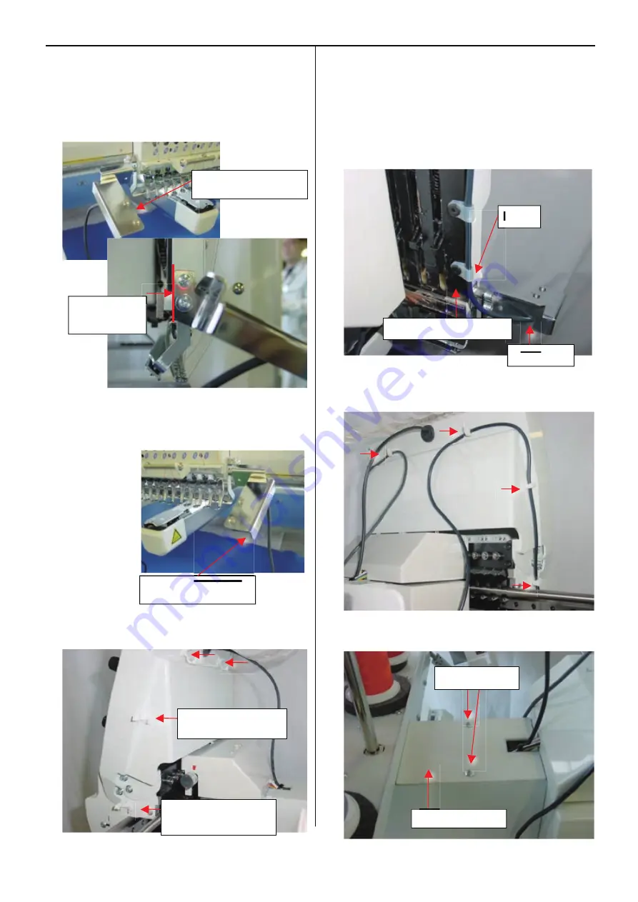
Fix safety sensor optical receiver to the stud on
the left side with the mounting screws removed
at the step 1.
4.
Fix safety sensor emission to the stud on the
right side with the mounting screws removed at
the step 1.
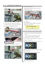
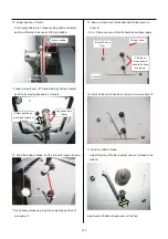
5. Attach clamp A to fix head on both right and left
sides. (Total 6 places)
6. Remove screws fixed on needle bar boss check
plate and fix the safety sensors’ cord and
Clamp B with the screws on both right and left
sides.
<NOTE>
Lace the cord through concave portion of
safety sensors.
7. Fix safety sensors’ cord with clamp A on both
right and left sides.
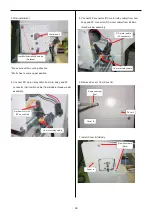
8.
Remove 2 screws and arm upper cover.
Concave portion
Safety sensor emission
(Right side)
Clamp B
Attach clamp A at the same
position on the left side of
moving head.
Attach clamp A at the same
position on the left side of
moving head.
Screws (2 places)
Install the safety
sensor so that this
surface is vertical
Needl bar boss check plate
Arm upper cover
Safety sensor optical receiver
(Left side)
Содержание HCD2-1501-40
Страница 1: ...Maintenance Manual for Embroidery Machine HCD2 1501 40 Version 2 3 HappyJapan Inc ...
Страница 10: ...10 HSA90311 Shell alvania EP Grease2 100g Page 31 33 36 M0404342 Needle height gauge Page 52 ...
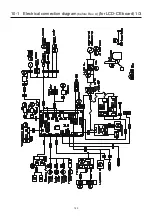
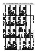
Страница 150: ...143 10 1 Electrical connection diagram before Rev A for LCD CE board 1 3 ...
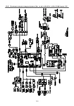
Страница 151: ...144 10 1 Electrical connection diagram before Rev A for LCD CE board 2 3 ...
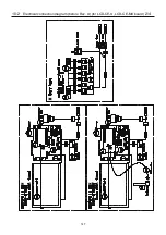
Страница 152: ...145 10 1 Electrical connection diagram before Rev A for LCD CE board 3 3 ...
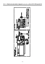
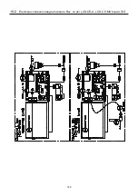
Страница 153: ...146 10 2 Electrical connection diagram before Rev A for LCD CE U LCD CE MX board 1 4 ...
Страница 154: ...147 10 2 Electrical connection diagram before Rev A for LCD CE U LCD CE MX board 2 4 ...
Страница 155: ...148 10 2 Electrical connection diagram before Rev A for LCD CE U LCD CE MX board 3 4 ...
Страница 156: ...149 10 2 Electrical connection diagram before Rev A for LCD CE U LCD CE MX board 4 4 ...
Страница 157: ...149a 10 2a Electrical connection diagram Rev A 1 4 ...
Страница 158: ...149b 10 2a Electrical connection diagram Rev A 2 4 ...
Страница 159: ...149c 10 2a Electrical connection diagram Rev A 3 4 ...
Страница 160: ...149d 10 2a Electrical connection diagram Rev A 4 4 ...
Страница 161: ...150 10 3 Connection of inverter Inverter set Inverter set ...
Страница 165: ...153 HCD8116 TP SW Circuit Board Ass y HCD8124 TC8 7 Circuit Board Ass y Rev A ...
Страница 166: ...154 HCD8119 y ...
Страница 198: ...2017 8 HappyJapan Inc 9 5 TAITO 2 CHOME TAITO KU TOKYO JAPAN TEL 81 3 3834 0711 FAX 81 3 3835 8917 ...

