110
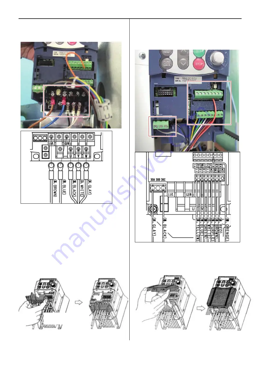
3. Tighten screws with screwdriver to install power cable and
motor cable per the following connection diagram.
(Cable color: GLAY, WHITE BLACK, BLUE, and BROWN)
4. Set
main terminal cover
Install main terminal cover
Hold both left and right ends of main terminal cover
with fingers and install the cover in the inverter
<Note>
Install main terminal cover not to apply stress to the
cable. If stress is applied to the cable, load is
applied to the screws for the main terminal and the
screws might be loosened.
5. Tighten screw and connect 10 cables the following
connection diagram. (Cable color: ORANGE, RED,
BROWN, PURPLE, WHITE, GREEN, BLUE, YELLOW,
BLACK, and GLAY)
6. Install control terminal cover
Install the cover by inserting the nail on top of the cover to
the ditch of the inverter.
Do not pinch any cables with the cover.
Main terminal cover
Содержание HCD2-1501-40
Страница 1: ...Maintenance Manual for Embroidery Machine HCD2 1501 40 Version 2 3 HappyJapan Inc ...
Страница 10: ...10 HSA90311 Shell alvania EP Grease2 100g Page 31 33 36 M0404342 Needle height gauge Page 52 ...
Страница 150: ...143 10 1 Electrical connection diagram before Rev A for LCD CE board 1 3 ...
Страница 151: ...144 10 1 Electrical connection diagram before Rev A for LCD CE board 2 3 ...
Страница 152: ...145 10 1 Electrical connection diagram before Rev A for LCD CE board 3 3 ...
Страница 153: ...146 10 2 Electrical connection diagram before Rev A for LCD CE U LCD CE MX board 1 4 ...
Страница 154: ...147 10 2 Electrical connection diagram before Rev A for LCD CE U LCD CE MX board 2 4 ...
Страница 155: ...148 10 2 Electrical connection diagram before Rev A for LCD CE U LCD CE MX board 3 4 ...
Страница 156: ...149 10 2 Electrical connection diagram before Rev A for LCD CE U LCD CE MX board 4 4 ...
Страница 157: ...149a 10 2a Electrical connection diagram Rev A 1 4 ...
Страница 158: ...149b 10 2a Electrical connection diagram Rev A 2 4 ...
Страница 159: ...149c 10 2a Electrical connection diagram Rev A 3 4 ...
Страница 160: ...149d 10 2a Electrical connection diagram Rev A 4 4 ...
Страница 161: ...150 10 3 Connection of inverter Inverter set Inverter set ...
Страница 165: ...153 HCD8116 TP SW Circuit Board Ass y HCD8124 TC8 7 Circuit Board Ass y Rev A ...
Страница 166: ...154 HCD8119 y ...
Страница 198: ...2017 8 HappyJapan Inc 9 5 TAITO 2 CHOME TAITO KU TOKYO JAPAN TEL 81 3 3834 0711 FAX 81 3 3835 8917 ...


