Hanwell Smart Receiver 2 (SR2)
Instruction Manual
IM6001 - 3
Page 14 of 22
hanwell.com
6
Additional Connections
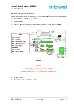
The SR2 can be connected to other Hanwell or 3rd Party devices. These are connected using
the spring-loaded input sockets
JP2
,
JP12
and
JP13
. See
6.1
Alarm Relays
The
SR2
has three on-board relay outputs that can be used to send alarm notification to a
beacon or via an auto-dialer (or other 3rd party device).
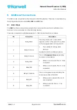
These are connected via JP2 (See Appendix 1 – SR2 Connection Data), as follows:
Pin Connection
Description
1
Relay 1 N/O
This relay closes and a nominal 12V
appears on Pin 1 in the event of any alarm
on the assigned Grids. It is fused via F1.
This suitable for driving alarm
beacons.
See Section 5.3 for additional options.
2 Relay
Common
3 Relay
Common
This is a
Changeover Relay
responding
to alarms in the software.
When no alarms exist, Pins 3 + 5 are
connected.
When an alarm exists, Pins 3 + 4 are
connected.
4
Relay 2 NC
5 Relay
NO
6
Relay 2 Common
This is a changeover relay indicating the
mains power state of the SR2.
When power is present Pins 6 + 8
are connected.
When power fails Pins 6 + 7 are
connected.
7 Relay
NC
8 Relay
NO
Содержание IM6001
Страница 1: ...hanwell com IM6001 Hanwell Smart Receiver 2 SR2 User Manual ...
Страница 2: ...Intentionally Blank ...
Страница 25: ......


