background image

Hanwell Smart Receiver 2 (SR2) 

Instruction Manual 


hanwell.com


Page 11 of 22 

IM6001 - 3


Caution! 

The UPS Backup Battery Float Charge has been adjusted to provide 1.5v to the battery. If the 

battery is changed to another type or manufacturer, then the Float Charge MUST be changed 

to suit the new battery. 

Failure to do so may cause irreparable damage. 

4.4


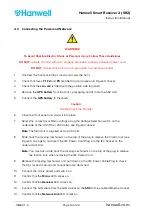
Configuring the SR2 Receiver’s Network Settings 

Configuration is normally done on the network but, in some instances, it may be necessary to 

connect to the 

Smart Receiver(s)

 directly. 


Before the 

Smart Receiver(s)

 can be configured, fixed IP addresses should be assigned 

to each unit by the Network Manager. 


For information on setting up an SR2 with an IP address for use with EMS or 

Synergy, please refer to Appendix 2 of this document. 


You should also know the 

Subnet

 and 

Gateway

 addresses. 


The Smart Receiver should be connected to the network using a straight-through 

network lead (supplied). 

Refer to the Section - Configuring the Smart Receiver on a Network of the EMS Online User 

Guide: 

http://www.help.emsprocloud.com/index.html?configuring-the-smart-receiver.html

 for 

details on how to assign an IP address to an SR2. 


The SR2 is now ready to use. 


Sections 5 and 6 of this Document contain optional additional settings and connections. 

Содержание IM6001

Страница 1: ...hanwell com IM6001 Hanwell Smart Receiver 2 SR2 User Manual ...

Страница 2: ...Intentionally Blank ...

Страница 3: ...r IM6001 Issue No Issue Date Changes By 1 11 July 2018 First release IR 2 23 October 2018 Addition of Appendix 3 and minor amendments IR 3 20 February 2019 Addition of information on IEC mains inlet socket and voltage selection switch IR 4 17 June 2019 Addition of Cautions Warnings and additional specifications IR ...

Страница 4: ...onnecting the Power and Network 10 4 4 Configuring the SR2 Receiver s Network Settings 11 5 Advanced SR2 Configuration 12 5 1 Fall Back Operation 12 5 2 On Board Sensors 12 5 3 Alarm Relay Operation 12 5 4 Sensor Groups 13 5 5 Transmitter Preamble 13 6 Additional Connections 14 6 1 Alarm Relays 14 6 2 MS1000 Control Panel 15 6 3 On Board Sensors 15 7 Maintenance 17 7 1 Uninterruptable Power Supply...

Страница 5: ...ll the Hanwell Smart Receiver 2 SR2 Unit The SR2 is a Network Enabled Receiver designed for collecting environmental monitoring data from multiple points within a site In addition it can be upgraded to a Transceiver which both receives and re transmits data It uses the standard TCP IP communications protocol for rapid data handling ...

Страница 6: ...see Figure 3 overleaf 1 x UPS battery unless an external one is to be used 1 x External Receiver Unit boxed separately USB SP2 USB stick containing relevant manuals including IM6001 this document If you are missing any of these items please contact Hanwell Solutions Ltd see Section 8 You will also need the EMS application installed on your System 2 2 SR2 Unit Ratings Voltage Frequency Current Powe...

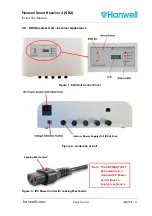
Страница 7: ...SR2 Receiver Unit External Appearance Figure 1 SR2 Unit Control Panel Figure 2 Underside of Unit Figure 3 IEC Power Cord with Locking Mechanism Locking Mechanism Internal Power Supply Unit PSU Fuse Note The SR2 MUST NOT be powered via a standard IEC Power Cord without a locking mechanism ...

Страница 8: ...isites The following pre requisites assume that a final location for the SR2 s has been identified following a Radio Survey If this is not the case then the following should be factored in when deciding the SR2 s final location There should be A 24 hour mains power outlet within 1 5m of the planned location An enabled 10 100 Base T LAN socket at the planned location Note If this is greater than 1m...

Страница 9: ...n which the software will run IP Address For example 192 168 1 100 _ _ _ _ _ _ _ _ _ _ _ _ Subnet For example 255 255 255 0 _ _ _ _ _ _ _ _ _ _ _ _ Gateway For example 192 168 1 1 _ _ _ _ _ _ _ _ _ _ _ _ If the IT Department requires a MAC address in order to assign an IP address contact Hanwell Solutions Ltd to request it see Section 8 The MAC address is also listed on a label on the daughter PCB...

Страница 10: ...e for details on this http www help emsprocloud com index html configuring the smart receiver html In addition you can also change the Default Hardware Settings of the SR2 see Section 5 or connect Local Sensors see Section 5 2 4 1 Wall mounting the SR2 The SR2 has a keyhole and four screw holes in is rear plate These should be used for wall mounting the Unit Note We recommend the radio reception a...

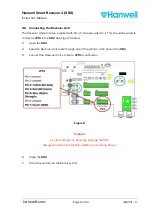
Страница 11: ...hould be wired to connector JP14 in the SR2 See Figure 5 below 3 Open the SR2 4 Feed the Receiver Unit cable through one of the glands in the base of the SR2 5 Connect the Receiver Unit s cable to JP14 as outlined in Figure 5 Caution Incorrect Wiring can Seriously Damage the SR2 Always Double Check the Wiring Before Connecting Power 6 Close the SR2 7 Screw the aerial onto the Receiver Unit ...

Страница 12: ... and screw it into place 7 Select the correct local Mains voltage using the Voltage Selection switch on the underside of the Unit 115 or 240 Volts see Figure 2 above Note The SR2 Unit is supplied set to 240 Volts 8 Slide back the locking mechanism on the top of the plug to release the friction lock see Figure 3 on page 5 and insert the IEC Power Cord Plug into the IEC Socket on the underside of Un...

Страница 13: ...the Smart Receiver s can be configured fixed IP addresses should be assigned to each unit by the Network Manager For information on setting up an SR2 with an IP address for use with EMS or Synergy please refer to Appendix 2 of this document You should also know the Subnet and Gateway addresses The Smart Receiver should be connected to the network using a straight through network lead supplied Refe...

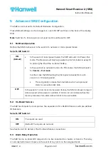
Страница 14: ...the SR2 will switch to Comms Fail mode In either case the SR2 will log the first signal received from each sensor in a 10 minute period This will greatly increase the time before which wraparound starts to overwrite older data OFF In the event of a Comms or mains power failure the SR2 continues to log all data received while power is available If Comms is not restored when the memory becomes full ...

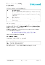
Страница 15: ...ups EMS has the capability to group sensors of the same type together into Sensor Groups Sensor Groups are also used to control SR2 Alarm Relays and associated MS1000 Control Interface outputs via the Local Alarms settings For details on creating editing and managing Sensor Groups refer to the Sensor Groups section of the EMS Online User Guide http www help emsprocloud com index html sensor topics...

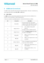
Страница 16: ...nection Data as follows Pin Connection Description 1 Relay 1 N O This relay closes and a nominal 12V appears on Pin 1 in the event of any alarm on the assigned Grids It is fused via F1 This suitable for driving alarm beacons See Section 5 3 for additional options 2 Relay Common 3 Relay Common This is a Changeover Relay responding to alarms in the software When no alarms exist Pins 3 5 are connecte...

Страница 17: ...ts for local probes the equivalent of 4 x RL2000 Sensors with pre defined ID numbers The probes should be connected to JP13 See Appendix 1 SR2 Connection Data as follows Radio Sensor Type EMS ID No Channel Probe Connections RL2000 Dual Thermistor 200 Thermistor A Pin 1 positive Pin 2 GND Thermistor B Pin 3 positive Pin 4 GND RL2000 RH Thermistor 201 RH Pin 5 5V Pin 6 signal Pin 8 GND Thermistor Pi...

Страница 18: ...cy of 3 For greater accuracy you should use RL4000 or RL5000 radio sensors 0 2 C and as standard Note on Stability If the Thermistor or RH channels produce unstable results fit a 10μF tantalum electrolytic capacitor across the relevant terminals This operation is polarity sensitive so the capacitors should be fitted as follows EMS Sensor Type Channel Capacitor Connections RL2000 Dual Thermistor Th...

Страница 19: ...rer s recommended voltage To Adjust the Battery Float Voltage 1 Fit the new battery and allow to charge for several hours 2 Measure the voltage across the battery terminals 3 Adjust variable resistor VR 1 See Appendix 1 SR2 Connection Data until the measured voltage meets the manufacturer s recommended voltage 7 2 Coin Cell Battery The coin cell ensures uninterrupted power to the clock chip It sho...

Страница 20: ...ons Limited Pendle House Jubilee Road Letchworth Hertfordshire SG6 1SP Tel 01462 688070 Email sales hanwell com Web www hanwell com For Technical Support Tel 01462 688 078 Email support hanwell com EU Overseas Customers Please contact your local Hanwell Distributor A list of distributors is available at www hanwell com global distributors ...

Страница 21: ...Hanwell Smart Receiver 2 SR2 Instruction Manual hanwell com Page 19 of 22 IM6001 3 Figure 6 Appendix 1 SR2 Connection Data ...

Страница 22: ...lier SR2 Serial Numbers starting later than 0415 To set up an SR2 for use with EMS or Synergy 1 Download the Wiznet Configuration Utility from www supportftp Hanwell com Utilities SRNetworkConfig zip Note The PC you download the Utility to must be on the same LAN as the SR2 being setup 2 Run the Utility 3 Click on the Configuration Tool toolbar to populate the Board List 4 Highlight the Mac addres...

Страница 23: ...nable Serial Debug Mode tick box 6 Enter values into the highlighted fields on the Network tab as shown in Figure 9 above 7 Enter values into the highlighted fields on the Serial tab as shown in Figure 10 below Figure 10 8 Enter values into the highlighted fields on the Option tab as shown Figure 11 below ...

Страница 24: ...iver 2 SR2 Instruction Manual IM6001 3 Page 22 of 22 hanwell com Figure 11 9 Once all the changes have been made click on to save The windows shown in Figure 12 below will be displayed as the changes are saved Figure 12 ...

Страница 25: ......
Отзывы: