


User Manual 71
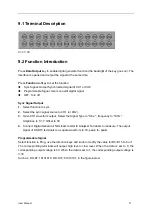
9.1 Terminal Description
Vcc: 3.3V
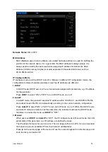
9.2 Function Introduction
Press
Data Output
key to enable digital generator function (the backlight of the key goes on). The
interface is opened and output the signal at the same time.
Press
Function
softkey to set the function.
Sync Signal: Output Synchronized signal of CH1 or CH2.
Programmable Signal: Users can edit digital signal.
OFF: Turn off
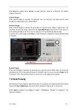
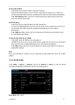
Sync Signal Output
1.
Select function to sync.
2.
Select the sync signal source to CH1 (or CH2).
3.
Open CH1 waveform output, Select the Signal Type to "Sine ",
frequency to “1KHz”,
Amplitude to 1V, Y Offset to 0V.
4.
Connect Digital Generator Terminals to LOGIC Analyzer Terminals to measure. The output
signal of D0-D15 terminals is a square waveform (3.3V, peak- to- peak).
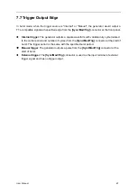
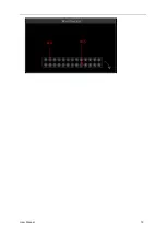
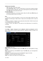
Programmable Signal
Select function to Prog, use the direction keys and knob to modify the value for D0~D15 to 0 or 1.
The corresponding terminals will output high level or low level. When the data is set to 0, the
corresponding output voltage is 0V. When the data is set to 1, the corresponding output voltage is
3.3V.
Such as, D0~D7: 10101010, D8~D15: 01010101, in the figure below.