


User Manual 21
period.
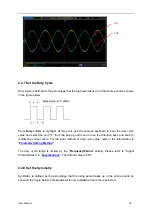
The pulse width and pulse duty cycle are correlative. Once a parameter is changed, the other will
be automatically changed. The pulse duty cycle is limited by the "Minimum Pulse Width" and
"Pulse Period".
1.
2.
- 2 × Minimum Pulse Width ÷ Pulse Period) × 100%
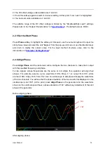
Press
Width/Duty
to highlight "Width". At this point, use the numeric keyboard to input the desired
value and select the desired unit from the pop-up unit menu or use the direction keys and knob to
modify the current value.
1.
2.
3.
switch to the duty setting.
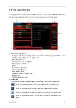
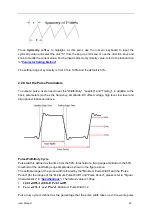
Leading/Trailing Edge Time
The leading (rising) edge time is defined as the time required for the pulse amplitude to rise from
10% threshold to 90% threshold; while the trailing (falling) edge time is defined as the time
required for the pulse amplitude to fall from 90% threshold to 10% threshold as shown in the
figure above.
The range of the leading/trailing edge time is limited by the pulse width currently specified as
shown in the formula below. The edge time will be automatically adjusted to match the specified
pulse width if the value currently set exceeds the limit value.
Leading/Trailing Edge Time ≤ 0.625 × Pulse Width
Press
Leading
/
Trailing
softkey to highlight.
Use the numeric keyboard to input the desired value and select the desired unit from the pop-up
unit menu or use the direction keys and knob to modify the current value.
1.
2.
g edge time units: sec, msec, μsec and nsec.
3.
set them separately.
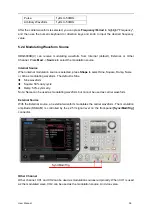
2.2.10 Enable the Channel Output
After configuring the parameters of the waveform selected, waveform output could be enabled.
Press
1Output
or/and
2Output
at the front panel and the backlight of the button turns on. The
instrument outputs the configured waveform from the
[1]
or/and
[2]
connector at the front panel.
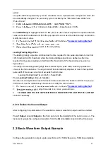
2.3 Basic Waveform Output Example
Configure the generator to output a pulse waveform with 1.5MHz frequency, 500mVpp amplitude,