III
CE model: optional maximum lifting height 6000 mm
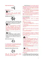
Careful
Bearing capacity chart
This
chart
shows
the
relationship between the location
of the load center distance and the
maximum load. Before loading,
check whether the load and load
center distance are within the
allowable
range
of
bearing
capacity chart. If the shape of the
load is complex, place the heaviest
part of the load in the center of the
fork and close to the shelf.
Note; The vehicle tonnage value shown below is based on the load center distance of
500mm.
Model
Engine
Hydraulic
transmission
Load
center(mm)
CPCD30/35-XW43E-RT
Cummins
QSF2.8T3NA49
Diesel engine
RTE350-120000-G00
CPCD25-XW43E-RT
RTE250-120000-G00
CPCD30/35-XW43C-RT4
RTE350-120000-G00
CPCD25-XW43C-RT4
RTE250-120000-G00
CPCD30/35-XW33E-RT
4TNE98-BQFLC
Diesel engine
RTE350-120000-G00
CPCD25-XW33E-RT
RTE250-120000-G00
CPCD30/35-XW33C-RT4
RTE350-120000-G00
CPCD25-XW33C-RT4
RTE250-120000-G00
CPCD30/35-XW98C-RT4
Kubota
V2607-CR-TE5
B
Diesel engine
RTC350-120000-G00
CPCD30/35-XW98E-RT2
RTE350-120000-G00
CPCD25-XW98C-RT4
RTC350-120000-G00
CPCD25-XW98E-RT2
RTE250-120000-G00
©
11/2019 HANGCHA GROUP CO., LTD
Act
ua
l L
ifti
ng
C
ap
aci
ty
mm
Mast Model
RATED CAPACITIES AND LOAD GENTRES GRAPH
Load Center Distance B
Capacity With Mast Vertical
mm
kg
Attachment Model
Max.Lift Height A
Serial No.
RT
FOR INDUSTRIAL USE - ACCORDING TO STANDARD ISO 22915-2
FOR ROUGH TERRAIN USE - ACCORDING TO STANDARD ISO 22915-13
kg


