26
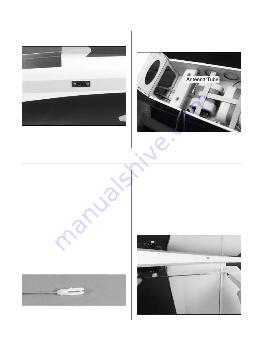
Step 12
Mount the radio switch in the side of the fuselage.
Step 13
Route the antenna to the rear of the fuselage
using the preinstalled antenna tube.
Required Parts
• Fuselage assembly
• Wing assembly
• Nylon clevis w/retainer (4) • Nylon wire keeper (4)
• 2-56 x 1/2" screw (6)
• Nylon control horn (4)
• Heavy-Duty Servo Arm (JRPA215) (4)
• 7
7
/
8
" (200mm) pushrod wire (4)
• #2 x 3/4" sheet metal screw (6)
Required Tools and Adhesives
• Drill
• Drill bit: 1/16" (1.5mm), 3/32" (2.5mm)
• Phillips screwdriver (small)
Step 1
Slide a clevis retainer onto a nylon clevis. Thread a clevis
onto a 7
7
/
8
" (200mm) wire a minimum of 10 turns.
Step 2
Attach a heavy-duty servo arm (JRPA215) to the elevator
servo. Remove the back plate from a control horn
using side cutters or a sharp hobby knife. Attach the
clevis to the outer hole of the control horn. Position
the control horn on the elevator so the horn aligns
with the hinge line of the elevator. The pushrod should
be parallel to the outside of the fuselage when the
pushrod rests on the servo arm. Mark the position
for the mounting holes using a felt-tipped pen.
Section 8: Servo Installation
Section 9: Linkage Installation


