background image

94

GENERAL fLyING

Super Decathlon is a very docile model in the air and on 

the ground. Takeoffs are easy and landings are slow and 

gentle and very predictable.

Begin by placing the model on the ground. Check all 

control throws and ensure everything is traveling in the 

correct direction. Move your idle trim up to a moderate 

idle. Taxi into position on the runway, facing into the wind. 

Apply power slowly and steer with rudder. The tail will 

come up very quickly.

As you apply full throttle and come to speed, apply a 

slight amount of up elevator and the Super Decathlon 

should lift off gently and begin to climb upwards. As you 

climb out, release the elevator and maintain a gentle 

climb to about 100 feet of altitude.

Once at about 100 feet of altitude, trim the model for lev-

el flight at 5/8 throttle. You will find the Super Decathlon 

to be very gentle on the controls and feel quite light on 

the sticks. The model is capable of all the basic aerobatic 

maneuvers; loops, rolls, stall turns, inverted flight, etc.

We hope you enjoy your Hangar 9

®

 Super Decathlon as 

much as we have.

fLIEGEN

Die Super Decathlon ist ein sehr gutmütiges Modell 

beim Fliegen und am Boden. Der Start ist einfach und 

die Landungen sind Dank geringer Geschwindigkeit sehr 

berechenbar.

Beginnen Sie mit der Voflugkontrolle, prüfen Sie alle 

Ausschläge und versichern sich, dass diese in die richtige 

Richtung laufen. Stellen Sie die Leerlaufdrehzahl richtig 

ein. Rollen Sie in Startposition gegen den Wind. Geben Sie 

langsam Gas und halten die Startrichtung mit dem Seit-

enruder. Das Heck des Flugzeuges wird schnell abheben.

Haben Sie Vollgas gegeben und die Abhebegeschwin-

digkeit erreicht, ziehen Sie etwas am Höhenruder und 

die Super Decathlon wird abheben und in den Steigflug 

übergehen. Nach dem ersten Steigflug lassen Sie das 

Höhenruder etwas nach und steigen langsam weiter auf 

ca. 30 Meter Höhe. 

Trimmen Sie in dieser Höhe bei 5/8 Gas das Modell aus. 

Sie werden feststellen, dass das Modell sehr gutmütig re-

agiert und leicht zu fliegen ist. Sie können mit der Super 

Decathlon Basiskunstflugmanöver wie Loopings, Rollen 

Turns, Rückenflug etc.. fliegen.

Wir hoffen das Sie an der Super Decathlon so viel Freude 

wie wir haben.    

GéNéRALITéS CONCERNANT LE VOL

Le Super Decathlon est un appareil très docile en l’air 

comme au sol. Les atterrissages et les décollages sont 

très faciles et lents.

Commencez par poser le modèle au sol. Contrôlez que 

toutes les gouvernes fonctionnent dans la bonne direc-

tion. Montez votre trim des gaz pour obtenir un ralenti 

soutenu. Roulez au sol face au vent. Augmentez les gaz 

progressivement en compensant à la dérive. La queue 

doit se lever rapidement.

Une fois que vous êtes plein gaz et que vous avez pris de 

la vitesse, tirez légèrement sur la profondeur et le Super 

Decathlon va quitter le sol tranquillement et prendre de 

l’altitude. Une fois que l’avion commence à prendre de 

l’altitude, relâchez la profondeur et continuez de grimper 

tranquillement jusqu’à environ une altitude de 30m 

environ.

Une fois que vous êtes à 30m d’altitude, trimez le modèle 

de façon a voler à plat avec 5/8 des gaz. Vous trouverez 

que le Super Decathlon est un avion très doux et qu’il 

semble très léger aux manches. Ce modèle est capable 

d’effectuer des manoeuvre de voltige basiques ; boucles, 

tonneaux, vol tranche, vol dos, ect.

Nous espérons que vous prendrez autant de plaisir avec 

votre Super Decathlon Hangar 9 que nous! 

GENERALITA’ SUL VOLO

Il Super Decathlon è un modello molto docile sia in aria 

che a terra. I decolli sono facili e gli atterraggi lenti e dolci 

ed anche molto prevedibili.  

Iniziare posando il modello a terra. Controllare tutte le 

corse dei comandi accertandosi che tutti vadano nella 

giusta direzione. Posizionare il trim del minimo fino ad 

avere un minimo moderato. Rullare in pista fino alla po-

sizione controvento per il decollo. Applicare gradualmente 

potenza contrastando la coppia con il timone. La coda si 

alza quasi subito.  

Dando tutto gas e aumentando la velocità, basta dare 

poco comando di elevatore per far salire dolcemente il 

Super Decathlon per fare quota. Appena si inizia la salita 

si può lasciare il comando dell’elevatore mantenendo un 

graduale rateo di salita fino a circa 30 metri.  

Raggiunta questa quota, trimmare il modello in modo da 

livellare il volo con circa il 60% di motore. Si troverà che 

il Super Decathlon ha un volo molto dolce e risponde ai 

comandi in modo molto graduale. Questo modello è in 

grado di eseguire tutte la manovre basiche di acrobazia 

come looping, tonneau, stalli d’ala, volo rovescio, ecc.  

Speriamo che possiate divertirvi con il Super Decathlon 

Hangar 9, così come abbiamo fatto noi.

Содержание Composite QQ Yak-54 2.6m

Страница 1: ...1 Composite QQ Yak 54 2 6m Instruction Manual Bedienungsanleitung Manuel d utilisation Manuale di Istruzioni ...

Страница 2: ...den können sich möglicherweise Sachschäden UND geringe oder keine Gefahr von Verletzungen ergeben ACHTUNG Wenn diese Verfahren nicht korrekt befolgt werden ergeben sich wahrscheinlich Sachschäden UND die Gefahr von schweren Verletzungen WARNUNG Wenn diese Verfahren nicht korrekt befolgt werden ergeben sich wahrscheinlich Sachschäden Kollateralschäden und schwere Verletzungen ODER mit hoher Wahrsch...

Страница 3: ...r différents niveaux de danger lors de l utilisation de ce produit REMARQUE Procédures qui si elles ne sont pas suivies correctement peuvent entraîner des dégâts matériels ET éventuellement un faible risque de blessures ATTENTION Procédures qui si elles ne sont pas suivies correctement peuvent entraîner des dégâts matériels ET des blessures graves AVERTISSEMENT Procédures qui si elles ne sont pas ...

Страница 4: ... von Kindern gelassen werden da die Teile verschluckt werden könnten mit ernsthaften Verletzung zur Folge Avertissements relatifs à la sécurité Lisez et suivez toutes les instructions relatives à la sé curité avant utilisation Une utilisation inappropriée peut entraîner un incendie de graves blessures et des dégâts matériels Composants Utilisez uniquement des composants compatibles Si vous avez de...

Страница 5: ...en könnten Planen Sie sorgfältig ihren Flugweg vor dem Start CONSIGNES de sécurité concernant l utilisation Inspectez votre modèle avant chaque vol Surveillez les fréquences radio utilisées à proximité Soyez toujours courtois et respectueux des autres utilisateurs de la zone de vol Choisissez une zone dégagée de tout obstacle et suf fisamment grande pour voler en toute sécurité Contrôlez que la zo...

Страница 6: ...toff 2 56 Chape en plastique 2 56 Forcella in plastica 4 40 metal 4 40 Metall 4 40 Chape en métal 4 40 Forcella in metallo Machined Aluminum Jury strut attachment x4 Aluminium Strebenhalter x4 Chape de fixation de hauban usinée en alu minium 4 Attacco struttura in alluminio x4 Machined Aluminum Strut End x4 Aluminium Strebenanschluss x4 Embout de liaison de hauban en aluminium usiné x4 Finale stru...

Страница 7: ...sicurarsi rotazione libera Push tightly Fest drücken Serrez fortement Spingere forte Apply Oil Öl verwenden Appliquez du lubrifiant Applicare olio Attach Temporarily Vorübergehend anbrin gen Attachez temporaire ment Attaccare temporanea mente L R L R Apply threadlock Schraubensicherung slack verwenden Utilisez du frein filet Applicare fuido thread lock Assemble right and left Links und rechts mont...

Страница 8: ...es optionnels 10 Outils nécessaires 11 Avant de débuter le montage 12 Montage Assemblage du train d atterrissage et des entretoises des haubans 13 Assemblage de la charnière de la gouverne de direction et du guignol de commande 17 Assemblage des servos des gouvernes de profondeur du guignol de commande et des stabilisateurs 22 Assemblage du câble pull pull et du servo de la gouverne de direction 2...

Страница 9: ... HAN520002 Right Wing Panel QQ Yak 54 2 6m Comp 3 HAN520003 Left Wing Panel QQ Yak 54 2 6m Comp 4 HAN520004 Horizontal Stabilizer Set QQ Yak 54 2 6m Comp 5 HAN520005 Rudder QQ Yak 54 2 6m Comp 6 HAN520006 Landing Gear QQ Yak 54 2 6 m Comp 7 HAN520007 Wheel Pants QQ Yak 54 2 6m Comp 8 HAN520008 Wing Tube QQ Yak 54 2 6m Comp 9 HAN520009 Stabilizer Tube QQ Yak 54 2 6m Comp 10 HAN520010 Cowling QQ Yak...

Страница 10: ...unga servo da 152 4 mm 1 EFLAEC311 6 inch EC3 Extension Lead 2 SPMB2000LP LiPo Ignition Pack 2000mah 1 LiPo Zündakku 2000mAh 1 Batterie Li Po d allumage 2 000 mAh 1 Pacco per accensione LiPo 2000 mah 1 SPM4000LP LiPo Receiver Pack 4000mah 2 LiPo Empfängerakku 4000 mAh 2 Batterie Li Po de réception 4 000 mAh 2 Pacco per ricevitore LiPo 4000 mah 2 PAAPT08 Thin CA Dünnflüssiger Sekundenkleber Colle C...

Страница 11: ...hleifmaschine Embout de ponçage cylindrique Punta per scartavetratura Hobby knife 11 blade Hobbymesser mit Schneide Nr 11 Couteau de modélisme doté d une lame n 11 Taglierino lama n 11 Hobby scissors Hobbyschere Ciseaux de modélisme Forbici per modellismo Hook and loop strap and tape Klettriemen und Klettband Attaches auto agrippantes et ruban adhésif Fascette e nastro a strappo Tie Wraps Kabelbin...

Страница 12: ... verbunden haben Avant de commencer l assemblage Retirez toutes les pièces des sachets pour les inspecter Inspectez soigneusement le fuselage les ailes et les empennages Si un élément est endommagé contactez votre revendeur Si l entoilage présente quelques plis vous pouvez les lisser en utilisant le pistolet à air chaud HAN100 et le gant HAN150 ou le fer à entoiler HAN101 avec la chaussette de pro...

Страница 13: ...ing locations onto the wing 1 Using a drill and 1 16 inch bit drill the marked locations 2 Run the screws in and out of the mounting locations and apply thin CA to the holes to strengthen the wall 3 Aileron servo Tray installation ...

Страница 14: ...ces that are marked in picture above Using an 80 grit sandpaper sand the tabs off the tray pieces 6 Apply masking tape to the back of servo hatch to prevent it from being scratched while working on it Mark the center of the servo hatch and draw a line ...

Страница 15: ...ge of the servo hatch and mark the location on both sides Draw two lines just outside the mounting locations Servo tray needs to be confined between these two lines 9 Mark the center of the servo tray Aileron servo Tray installation ...

Страница 16: ...s to be in the center of the servo hatch just below the 27mm mark and between the marked boundary lines just outside the mounting locations Using Mercury M100XF CA glue the servo tray piece to the hatch Apply pressure and make sure it stays vertical until CA dries Do not use accelerator Use hobby knife and scratch the surface of all the pieces of the servo tray that will be glued together Using Ac...

Страница 17: ...nd glue pieces 2 and 3 one at a time Hold each piece under pressure until CA dries Cut the fiber glass strip provided to six pieces Aileron servo Tray installation 15 Above pictures show how these fiberglass pieces will be glued using finishing epoxy resin to strengthen the tray ...

Страница 18: ...ke sure cloth adheres properly with no gap or bubble to the servo tray sup port Following the same method do the right side of the servo tray support 18 Aileron servo Tray installation Mix finishing epoxy resin and brush it on the tray bracket then lay the fiber glass cloth and let it get wet Work the fiberglass cloth for a tight fit 16 ...

Страница 19: ...ethod fiberglass the servo tray piece to the tray bracket 20 21 Thoroughly scuff the tray and the hatch for this step as it is a very important part of this process Use acetone and clean the hatch Aileron servo Tray installation ...

Страница 20: ... once more 20 21 Once the fiberglass resin is cured using a hobby knife cut the excess fiberglass cloth Make all four servo trays using the same method As it has been stated be sure to thoroughly scratch the surfaces and then clean with acetone These steps are extremely important otherwise tray can break and cause flutter and loss of control of the model Aileron servo Tray installation ...

Страница 21: ...etween each two hinge Fold the tape and carefully apply to the hinge line Packing tapes are strong if removing the tape is necessary do so very carefully as not to take the paint off the surface 2 1 The aileron hinge line needs to be seal from the bottom Deflect the aileron fully and clean the bevels using alcohol swab Aileron Servo installation and Hinge line sealing ...

Страница 22: ... output shaft is closer to the aileron hinge line Run the servo mounting screws in and out of the tray and apply thin CA to holes 5 4 Prepare the servo by installing the rubber grommets and brass eye lets Aileron Servo installation Hinge line sealing ...

Страница 23: ...imentare temporaneamente i servi collegandoli al ricevitore Con il sub trim della radio su 0 montare il braccio del servo perpendicolarmente al servo Se necessario utilizzare il sub trim Apply thread lock to the servo arm center screw and make sure to use the lock washer provided with servo accessories Geben Sie etwas Schraubensicherungslack auf die mittlere Schraube des Servoarms Legen Sie eine d...

Страница 24: ...oo much and get close to the mounting location 11 Connect a JR Heavy Duty 18 inch extension to the outboard servo and a 6 inch to the inboard servo Use a string and masking tape to secure the connection Pass a rod through the root to the servo box and tape the servo extension to the rod and pull through the wing root 12 Aileron Servo installation and Hinge line sealing ...

Страница 25: ... the threaded rod provided 14 15 Adjust the ball links so that it measures 33 7mm between the end of ball links Make all the aileron linkages the same exact lengths Aileron Servo installation and Hinge line sealing Install the hatch ...

Страница 26: ...iver Aileron Servo installation and Hinge line sealing 17 18 Install the ball link on the servo arm using a crescent wrench and 3 32 inch ball driver Adjust the servo travel using a computerized transmitter or a JR MatchBox so that there is no binding throughout the travel of the aileron ...

Страница 27: ... mark the wheel pant set screw location Drill the marked location by using a 1 8 inch drill bit followed by a 5 32 inch drill bit 1 2 Landing Gear Wheel pants installation Install the blind nut by tightening the M3x10mm screw provided using a 2 5mm ball driver 3 ...

Страница 28: ...l install the 5mm bolt and a washer through the wheel Using a drill and 1 4 inch drill bit enlarge the wheel axle hole 5 4 On the other side of the wheel install 6 washers and the locknut 6 Landing Gear Wheel pants installation ...

Страница 29: ...un the bolt through the locknut Tighten enough to allow for the wheel to rotate with little friction 7 8 Pass the bolt through the wheel pant the landing gear leg and a washer and then locknut Using a vise grip hold the head of the bolt and with the help of a 10 socket wrench tighten the locknut 9 Landing Gear Wheel pants installation ...

Страница 30: ...tighten the wheel pant to the landing gear 10 Ensure both wheels move with little friction Pass the 5mm bolt through the washer and apply thread lock Using a 4 5mm hex driver tighten the landing gear bolts to the fuselage 11 12 Landing Gear Wheel pants installation ...

Страница 31: ...arefully insert the hinge rod into the hinges until it is flush with the bottom of the rudder Temporarily mount the phenolic T bracket so that the spring holes line up with the rudder control horn pivot point Using a felt pen mark the locations Rudder and tail gear Installation ...

Страница 32: ...d block location that tail gear will be mounted on Using a felt pen mark the screw mounting locations Run the screws in and out and apply thin CA to the holes to harden the wall Once CA is dry mount the T bracket Drill marked locations using a 1 8 inch drill bit rudder and tail gear Installation ...

Страница 33: ...s dried Hook up the springs to the T fitting and tiller arm Drill marked locations using a 1 8 inch drill bit Run the screws in and out Apply some thin CA in the holes and allow time for the glue to dry Rudder and tail gear Installation ...

Страница 34: ...stment 3 Using a inch wrench and 3 32 inch ball driver install the ball link on the last straight hole on the servo arm Rudder servo and pull pull cable installation Einbau von Höhenruderservo und Pull Pull Kabel Assemblage du câble pull pull et du servo de la gouverne de direction Installazione del servo del timone e DEI CAVETTI DI COMANDO ...

Страница 35: ...ower up the receiver Install the arm perpendicular to the output shaft Use sub trim if necessary 6 Cut the pull pull cable in half rudder servo and pull pull cable installation Einbau von Höhenruderservo und Pull Pull Kabel Assemblage du câble pull pull et du servo de la gouverne de direction Installazione del servo del timone e DEI CAVETTI DI COMANDO ...

Страница 36: ...pull cable through the brass sleeve eye bolt and loop back in the sleeve Rudder servo and pull pull cable installation Einbau von Höhenruderservo und Pull Pull Kabel Assemblage du câble pull pull et du servo de la gouverne de direction Installazione del servo del timone e DEI CAVETTI DI COMANDO ...

Страница 37: ...es exit straight 12 Tape the rudder at the center using masking tape and power on the servo by connecting it to the receiver Rudder servo and pull pull cable installation Einbau von Höhenruderservo und Pull Pull Kabel Assemblage du câble pull pull et du servo de la gouverne de direction Installazione del servo del timone e DEI CAVETTI DI COMANDO ...

Страница 38: ...e is no slack and crimp the brass fitting Make sure there s no slack in the cable if need be adjust the tension 15 Rudder servo and pull pull cable installation Einbau von Höhenruderservo und Pull Pull Kabel Assemblage du câble pull pull et du servo de la gouverne de direction Installazione del servo del timone e DEI CAVETTI DI COMANDO ...

Страница 39: ...xtension through the servo lead cut out of the stab 1 2 Prepare the servo by inserting the rubber grommets and eyelets Elevator servo and stab installation Using a rod with a hook at the end grab the servo extension and pull out through the servo opening 3 ...

Страница 40: ...secure the connec tor Then pull the extension through the servo lead opening 4 5 Mount the servo so that the output shaft is closer to leading edge of the stab Use a magnetic tip screw driver or a magnet and insert the screw 6 Elevator servo and stab installation ...

Страница 41: ...tighten the screws 7 Elevator servo and stab installation Temporarily power up the servo and mount the arm perpendicular to the servo output shaft Use sub trim if necessary 8 Use thread lock on the center servo screw and tighten the screw 9 ...

Страница 42: ...stall the servo arm set screws Elevator servo and stab installation 11 12 Prepare the ball links so that the length of the rod is 52mm between ball links Using a crescent wrench and 3 32 inch ball driver install the ball link onto the outermost hole in the Hangar 9 servo arm ...

Страница 43: ...driver install the ball link in the control horn 14 Use a 1 8 inch drill bit and drill a pilot hole in the fuselage 15 Using a pencil mark 23mm away from the center of the anti rotation pin hole in the fuselage Elevator servo and stab installation ...

Страница 44: ...ignation for right side and left side respec tively Plug the right stabilizer first into the stab tube and fuselage Using blue thread lock install the stab screw through the bottom of the stab into the tube 18 Pass the extension into the fuselage and leave the female lead outside If stabilizers will have to be removed for transportation use a commercially available safety clip to secure the servo ...

Страница 45: ...on the dome Extend these lines straight up and horizontal Measure 40mm up and down and 35mm left and right and mark the 4 mounting locations Temporarily mount the engine and make sure that marked locations line up with engine mounting tabs Engine dome preparation DA 120 ...

Страница 46: ... the hole Mark the top of the engine dome for ignition module and ignition battery installation by tracing the outside of the ignition box and battery Insert blind nuts and using a 4 5mm ball driver along with the 1 inch standoff needed for the engine installation pull the blind nuts in the engine dome Engine dome preparation for da 120 ...

Страница 47: ...e marked location just a little longer than the hook and loop strap width Drill a 3 8 inch diameter hole for ignition wires Start from smaller bits and increase one size at a time Install a rubber grommet with ID of 3 8 inch Engine dome preparation for da 120 ...

Страница 48: ... tape to the masking tape Apply masking tape to the back of ignition module then apply a servo tape strip to the masking tape Remove the backing of the servo tape and mount both the ignition and the battery Use a piece of hook and loop and secure them 3 Ignition module and battery installation ...

Страница 49: ...sembly and dry fit the pieces together Thoroughly scratch the mating surfaces with a hobby knife Mix epoxy and micro balloons and glue the pieces together Using a small clamp hold the pieces together for better adhesion Throttle servo installation ...

Страница 50: ...lind nuts using the M3x16mm screws and 2 5mm ball driver Insert the servo into the tray and mark the mounting locations Dry fit the throttle servo if there is any binding use a small file and open up the servo tray Throttle servo installation ...

Страница 51: ...the servo screws in the holes and back them out Apply thin CA wait until CA dries and mount the throttle servo Temporarily mount the engine Enlarge the hole in the DA throttle arm by using 3 32 inch and 7 64 inch drill bits respectively Throttle servo installation ...

Страница 52: ... then remove the engine Prepare the throttle rod by installing the clevis and ball link Measure 98mm between ball link and clevis and using a felt pen and mark the end of the clevis on the threaded rod This is an approximate length and may need adjusting depending of the location of the servo tray Remove the clevis 12 Throttle servo installation ...

Страница 53: ... the engine on the 1 inch stand offs Pass the rod through the engine dome Connect the ball link to the engine throttle arm Add a piece of fuel tubing to the shaft of the clevis to secure the clevis at final stage of installation Throttle servo installation ...

Страница 54: ...moving the throttle tray Using a felt pen mark the tray location Using pin vise mark the mounting locations Temporarily mount the servo tray and connect the throttle servo arm to the servo Drill the dome for servo tray mounting locations using 3 32 inch and 7 64 inch drill bits Throttle servo installation ...

Страница 55: ...enlarge the hole for throttle rod in the dome Once satisfied remove the tray and apply thread lock to servo arm center screw and mount the arm Apply servo tape to the back of the throttle servo tray as shown in the picture above Mount the throttle servo tray using M3x16mm screws Finalize the installation by moving the piece of fuel tubing over the clevis Throttle servo installation ...

Страница 56: ... servo tape on one side of each battery Apply masking tape to both sides of each battery Using medium CA glue a piece of hook and loop to the other side of each battery 3 Receiver pack installation for DA 120 Stock Muffler setup ...

Страница 57: ...cture Mount the batteries with servo tape sitting on the tray and hook and look side on top Wrap the hook and look strap over the battery and ensure that hook and loop locks on top Note Battery locations shown are based on the equip ment that this manual is recommending and is built Receiver pack installation for DA 120 Stock Muffler setup ...

Страница 58: ... 1 2 Apply a piece of servo tape to the masking tape Apply masking tape to the back of ignition regulator Mount the regulator in front of the receiver battery 3 Ignition regulator and switch installation ...

Страница 59: ...ed area If need be change blade often Using a felt pen trace the area where the ignition switch is to be installed Install the switch A piece of plywood from the servo trays could be used for backing 6 Ignition regulator and switch installation ...

Страница 60: ...uded by passing them over the tank tray and into the slots Mark the fuel line exit to the carburetor inside of the dome Using a drill and 1 8 inch 7 32 inch drill bits and drill through the marked location Attach the Hangar 9 fuel filter to the line 3 Fuel tank installation for stock muffler ...

Страница 61: ...cation shown in above picture for fuel vent line Pass the vent line through the hole Pass the vent line through the hole Mark the location shown in above picture This is for the fill line Make sure it doesn t interfere with wing location Fuel tank installation for stock muffler ...

Страница 62: ...ding drum and a drill or a rotary tool open up the hole to 3 8 inch Using a drill and 1 8 inch drill bit drill through the marked location Install the Hangar9 fuel filler and T 9 Fuel tank installation for stock muffler ...

Страница 63: ...dome is on the fuselage Apply some thread lock to the studs Install the vibration dampeners on the dome Insert the clear tubes in the center of the vibration dampeners Insert the washer over the studs and using a 7mm nut driver tighten the nuts If using a socket make sure not to overtighten the nuts Using a nut driver as shown in the picture above is better 3 Engine dome installation ...

Страница 64: ...through the engine dome and connect to the engine carburetor Use a tie wrap to secure the line Using a felt pen draw a rectangle with width of 70mm 1 2 Using a felt pen mark the center of the cowl Engine dome installation Cowl preparation for stock muffler ...

Страница 65: ...n up the front of the cowl Use a sand ing drum and smooth out the corners 4 5 Carefully mount the cowl mark the spark plug cap contact location with the side of the cowl Trace the cowl blister on a piece of paper Cowl preparation for stock muffler ...

Страница 66: ...hine and reduce the size to 87 7 8 Using a hobby knife cut the paper following the line Trace the reduced blister size on the cowl such that spark plug contact area is inside the blister Cowl preparation for stock muffler ...

Страница 67: ...a cutting disk or a high speed drill and 1 16 inch drill bit 10 11 Install the cowl to ensure and check the blister location Using a rotary tool and sanding drum smooth out the edges make sure not to cross the traced line Cowl preparation for stock muffler ...

Страница 68: ...68 12 Clean the cowl using acetone 13 14 Glue the blister from inside of the cowl using goop or epoxy Use masking tape to hold in place Cowl preparation for stock muffler ...

Страница 69: ... cowl cut out for stock muffler installation Use the already cut stack as a reference for muffler cut out Dry fit the cowl often and open up the cowl as necessary Make sure not to force the cowl causing paint cracks The picture above shows the final result Cowl preparation for stock muffler ...

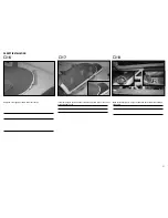
Страница 70: ...ded in the kit and find the best place to mount them for proper CG It is important that proper location of the battery trays and batteries be found before gluing the trays 1 2 Glue the mount using micro balloon and epoxy Tri Stocks help secure the mount in place Vent line from the tank should go straight down as shown in the pictures above Using a rotary tool and a cutting disk cut the engine dome...

Страница 71: ... of the landing gear needs to be opened up to accommodate for canister exits The picture above shows the canisters mounted 4 5 Fill line should be held on top and be away from the canisters Assemble the battery tray Canister Installation Option ...

Страница 72: ... Use medium CA to fill any remaining gap 7 8 Once the position of the battery is known glue the tray using epoxy and micro balloon Tray stands are cut such that to fit the round shape of the fuselage for proper contact Make sure to glue the round part of the leg to the fuselage The picture above shows the tray with battery installed Canister Installation Option ...

Страница 73: ...ch other where the receiver is to be installed 2 3 Glue a piece of hook and loop using medium CA Apply masking tape to the back of the receiver Receiver installation Einbau des Empfängers Installation du récepteu du récepteur Installazione del ricevitore ...

Страница 74: ...eiver over the masking tape 5 6 Once CA is dry mount the receiver Use servo tape to install the remote receivers The Picture above shows the location of remote receiver 1 Receiver installation Einbau des Empfängers Installation du récepteu du récepteur Installazione del ricevitore ...

Страница 75: ...ion of the remote receiver 2 8 9 Location of the remote receiver 3 Location of the remote receiver 4 Receiver installation Einbau des Empfängers Installation du récepteu du récepteur Installazione del ricevitore ...

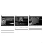
Страница 76: ...down any high spots at the seams or anywhere else to be smooth and flush with the surrounding area Use acetone and clean the surfaces 2 3 Carefully cut the edges of the canopy Note Canopy gets scratched easily be careful while cutting and moving the canopy Using 2 masking tape or mask paper mask the entire canopy Canopy installation ...

Страница 77: ...the inside of the canopy Follow the mold line and cut anything outside of the mold line by 1 16 inch Back of the canopy has two mold lines Cut anything outside the outer sec ond mold line Black solid lines show the two mold lines Canopy installation ...

Страница 78: ... 1 16 inch Black line shows the mold line 8 9 Remove the masking paper and mask the entire canopy with masking tape Mount the canopy in the canopy frame Make handles by folding a piece of masking tape This helps to move the canopy in the frame for final adjustment Canopy installation ...

Страница 79: ... the inside and one from the outside pinching the canopy For best result use 10 12 pairs of magnets Do not use tape Once the canopy is centered mark the edges using a felt pen Remove the canopy from the frame Using a hobby knife remove the masking tape below the marked line Canopy installation ...

Страница 80: ...he frame 14 15 Insert the canopy in the frame one last time for final adjustment and check It is extremely important that canopy sits flush with the frame with no to extremely minimum gap Once satisfied apply a bead of canopy glue Formula 560 to the canopy frame Canopy installation ...

Страница 81: ...ue Formula 560 to the canopy Insert the canopy in the frame and use magnets to hold in place Clean excess glue using damp cloth Mask the fuselage where canopy sits and open up the tab locations using a hobby knife Canopy installation ...

Страница 82: ...e canopy on the fuselage and wait 24 hours for the glue to fully cure Remove the masking tape and check the canopy for any excessive gap Fill the gaps with canopy glue and use the magnets to hold in place Canopy installation ...

Страница 83: ...ing tape and spread it over thoroughly Apply a bead of clear silicone to the canopy frame including front and back of the canopy Bolt the canopy to the fuselage Clean excess silicone that oozes out and wait 24 hours for the silicone to fully cure Canopy installation ...

Страница 84: ...asurement and location of the trims Dry fit the vinyl strip over the canopy and cut Apply commercially available sticker solution to be able to make adjustments if needed Mount the front and aft trims Work any bubble out Applying canopy trim ...

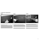
Страница 85: ...k the aileron extension wire location It s about 2 inch forward of the aft anti rotation pin location on the fuselage Using a drill and 1 8 inch drill bit make a pilot hole in the fuselage Using a sanding drum with 3 8 inch diameter enlarge the hole ...

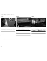
Страница 86: ...k the mounting hole locations onto the wing tip 3 Using a 1 16 inch drill bit and high speed drill or rotary tool make pilot holes It is very important to use a high speed rotary tool and increase the drill bit size with 1 16 inch at a time to finally get to 1 4 inch drill bit Optional side force generator installation ...

Страница 87: ...onal side force generator installation 5 6 Install the side force generator using screws and washers provided Install the inserts using a flat blade screw driver until it is flush with the wing tip Wipe excess glue using alcohol swab and ensure no glue gets inside the insert ...

Страница 88: ...re above shows the location of QQ Yak sticker on the fuselage 2 The picture above shows the stickers that go on the cowl and fuselage Sticker installation 3 The picture above shows the sticker that goes on the rudder ...

Страница 89: ...hat go on left and right wing panel Sticker installation Control surface measurement Control surface deflections are measured as pictured above Reference is the seam of control surface All measurements for low and high rates are given on page 91 ...

Страница 90: ...punkt des Flugzeugs justieren und das Modell richtig ausbalancie ren bevor Sie es fliegen Centre de gravité Une des opérations essentielles quant à la préparation de l appareil pour le vol consiste à équilibrer parfaitement le modèle 1 Fixez les panneaux des ailes au fuselage Assurez vous de raccorder les fils de l aileron aux câbles appropriés du récepteur Assurez vous qu aucun fil ne ressort du ...

Страница 91: ...vos davon ab in die Endausschläge zu laufen solange der Sender und Empfänger noch nicht verbunden sind Débattements 1 Mettez l émetteur et le récepteur sous tension Con trôlez les mouvements de la dérive en utilisant votre émetteur Quand le manche est vers la droite la dérive doit s orienter vers la droite Inversez la direction du servo à l émetteur si nécessaire 2 Contrôlez les mouvements de la p...

Страница 92: ...t beeinflußt werden Ist dieses der Fall fliegen Sie nicht Bauen Sie die RC Komponenten aus und lassen diese vom Hersteller überprüfen Checklist d avant vol Chargez la batterie de votre émetteur de réception et d allumage Utilisez le chargeur fourni avec votre ra dio Suivez les instructions fournies avec votre radio Charger votre radio la nuit qui précède la session de vol Chargez la batterie de l ...

Страница 93: ...ungen bewe gen kann Contrôles systématiques Contrôlez la tension de la batterie de l émetteur Ne volez jamais en dessous de la tension minimale recommandée par le fabricant Le faire pourrait entraîner un crash Quand vous contrôlez les batteries soyez certain de respecter les polarités avec votre voltmètre Contrôlez tous les accessoires guignols palonniers et chapes pour être sûr qu ils sont en bon...

Страница 94: ...ant le vol Le Super Decathlon est un appareil très docile en l air comme au sol Les atterrissages et les décollages sont très faciles et lents Commencez par poser le modèle au sol Contrôlez que toutes les gouvernes fonctionnent dans la bonne direc tion Montez votre trim des gaz pour obtenir un ralenti soutenu Roulez au sol face au vent Augmentez les gaz progressivement en compensant à la dérive La...

Страница 95: ...r auf freien Plätzen und beachten Sie alle Hinweise der Bedienungsanleitung des Modells wie auch der Fernsteuerung Garantiezeitraum Exklusive Garantie Horizon Hobby Inc Horizon garantiert dass das gekaufte Produkt frei von Material und Montagefehlern ist Der Garantiezeitraum entspricht den gesetzlichen Bestimmung des Landes in dem das Produkt erworben wurde In Deutschland beträgt der Garantiezeitr...

Страница 96: ...ue pour les composants électroniques et les moteurs Les réparations touchant à la mécanique en particulier celles des hélicoptères et des voitures radiocommandées sont extrêmement coûteuses et doivent par conséquent être effectuées par l acheteur lui même Periodo di garanzia Garanzia esclusiva Horizon Hobby Inc Horizon garantisce che i prodotti acquistati il Prodotto sono privi di difetti relativi...

Страница 97: ...contact your local city office your household waste disposal service or where you purchased the product Anweisungen zur Entsorgung von Elektro und Elektronik Altgeräten für Benutzer in der Europäischen Union Dieses Produkt darf nicht zusammen mit anderem Abfall entsorgt werden Stattdes sen ist der Benutzer dafür verantwortlich unbrauchbare Geräte durch Abgabe bei einer speziellen Sammelstelle für ...

Страница 98: ...prior to the specific event b An inexperienced pilot is assisted by an experienced pilot 4 When and where required by rule helmets must be properly worn and fastened They must be OSHA DOT ANSI SNELL or NOCSAE approved or comply with comparable standards B RADIO CONTROL RC 1 All pilots shall avoid flying directly over unprotected people vessels vehicles or structures and shall avoid endangerment of...

Страница 99: ...99 ...

Страница 100: ...ered trademarks of Horizon Hobby Inc DSMX is a trademark of Horizon Hobby Inc registered in the U S The Spektrum trademark is used with permission of Bachmann Industries Inc Saito is a trademark of Saito Seisakusho Co Ltd Japan All other trademarks service marks and logos are the property of their respective owners XXXXXX Created 2 2013 ...

Отзывы: