
Page 14
HQ Sweet Sixteen Service Manual
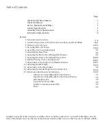
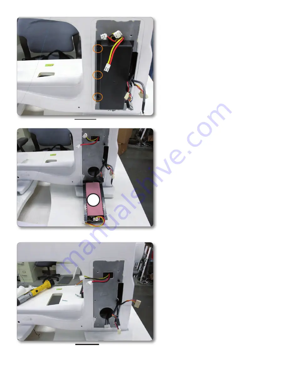
Figure 2.10
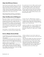
Figure 2.9
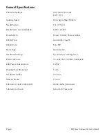
Figure 2.11
A
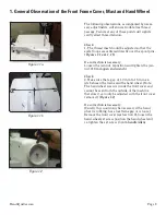
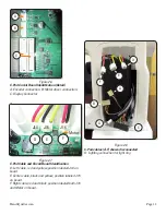
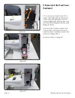
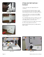
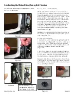
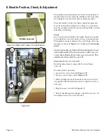
6. To remove power supply, loosen the 3
screws on the right side and remove the 3
screws on the left side (shown circled in
orange in
Figure 2.9
). Slide the power sup-
ply to the left and unplug the bottom cable.
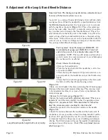
(
Figures 2.9-2.11
)
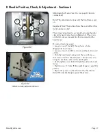
Important Note: Insulator material must
cover all metal on the back of the power
supply for proper insulating purposes. (See
position A in
Figure 2.10.
)
(Continue to Step 7 on page 18.)
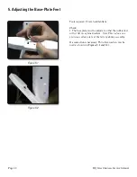
2. Removal of the Front Cover -
Continued


