
Page 10
HQ Sweet Sixteen Service Manual
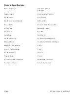
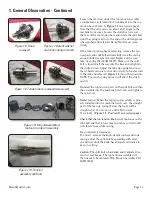
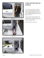
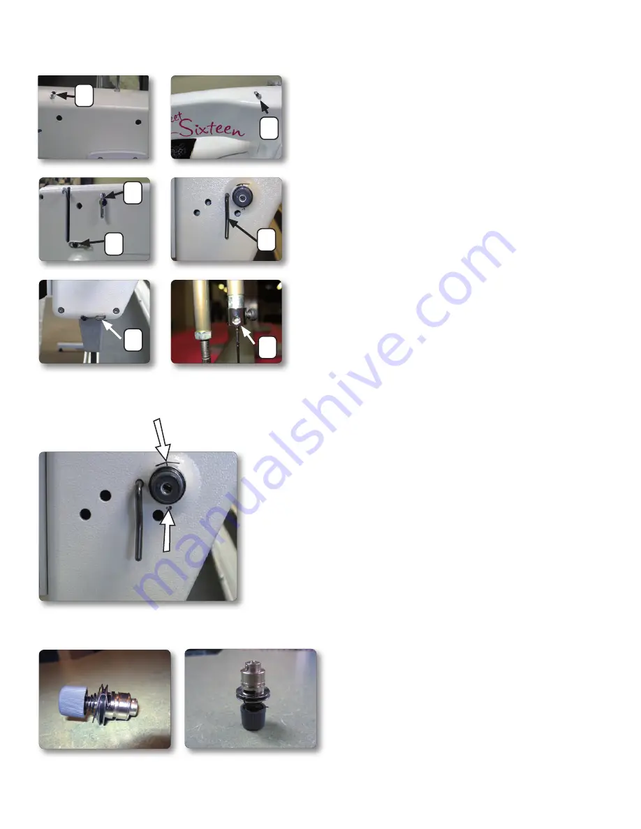
Figure 1.4
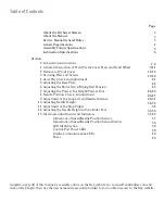
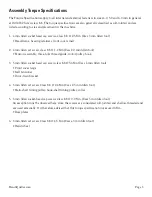
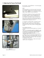
Figure 1.5. Top tension assembly, fully assembled
(two views)
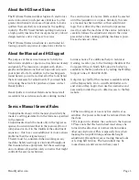
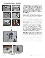
Figure 1.3
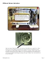
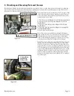
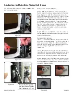
3.
Check/Inspect:
Test the condition of the thread guides
1, 2, 3, 4, thread stirrup 5, thread guide 6 and needle bar
thread guide 7 for any abrasions, cuts, or electroplating
blistering. Test each guide by fl ossing it with thread, left
to right and front to back in all directions, checking for
any sharp defects that may damage or cut the thread.
Replace any damaged parts.
(Figure 1.3)
(2 mm and 2.5
mm handle Allen)
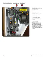
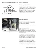
Check the top tension assembly for the following:
Check between the tension discs for any foreign material
that could prevent the discs from functioning properly.
If a correction is necessary:
Check the relative location of the knob before removing
the knob. Remove the knob, detent washer, tension discs
and cone spring. (See Figures 1.5 through 1.10.) Clear
and reassemble.
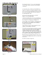
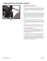
Note:
On very rare occasions, if the ma-
chine has been used an extreme amount, it is possible for
a groove to be worn into the tension discs. This will make
it impossible for the tension to be adjusted correctly
as the thread can pass through this worn groove in the
tension discs, while the unworn part of the discs touch,
resulting in no tension on the thread in the groove. This
may result in thread nests on the bottom of the quilt.
The top tension assembly will need to be replaced in this
instance. Top tension assembly part #QM10198.
Check:
That the take-up spring has a normal torsion ten-
sion and inspect the spring for any cuts, breaks or abra-
sions. When moved by hand and released, it should return
to the end of the cutout in the top tension assembly.
If a correction is necessary: (2 mm handle Allen, #1 fl at
screwdriver) (Figure 1.5)
Please Note: Tension knob may be either gray or black in
color.
B
A
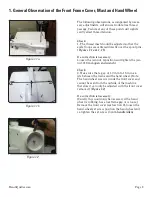
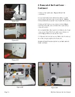
1. General Observation - Continued
1
2
3
4
5
6
7